EA KIT320F-8CTK ELECTRONIC ASSEMBLY, EA KIT320F-8CTK Datasheet - Page 22
EA KIT320F-8CTK
Manufacturer Part Number
EA KIT320F-8CTK
Description
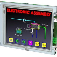
LCD Graphic Display Modules & Accessories Full Color Display Aluminum Bezel
Manufacturer
ELECTRONIC ASSEMBLY
Datasheet
1.EA_KIT320F-8CTK.pdf
(24 pages)
Specifications of EA KIT320F-8CTK
Pixel Density
320 x 240
Module Size (w X H X T)
154.6 mm x 114.8 mm x 29.5 mm
Viewing Area (w X H)
89.4 mm x 118.2 mm
Backlighting
CCFL
Background Color
Full Color
Product
Graphic LCD Module
Style
LCD Graphic Display
Interface
RS-232
Lead Free Status / RoHS Status
Lead free / RoHS Compliant


EA KIT320F-8 COLOR
COMMAND FOR ANALOGUE INPUTS
Table below shows functionality for analogue inputs AIN1 and AIN2. Range is 0..+250mV and
resolution is 10 bit (like a 3 digit DVM).
Command
Enable/disable analogue-in
Send analog value
Limit for analog macro
Bargraph for AIN1/AIN2
Redraw bargraph
Calibration
Scaling
Send string
Display on terminal
Display on graphic layer
String color
Font
Foom factor
Text pattern
Text angle
22
Codes
ESC
ESC
ESC
ESC
ESC
ESC
V
V
V
V
F
V
EA KIT320F-8: Commands for analogue AIN1, AIN2
@
W
O
G
M
A
D
K
R
L
U
B
E
S
T
V
F
Z
n1
ch
ch
ch
ch
ch
ch Format String... NUL
ch
ch
ch
ch
ch
ch
ch
ch
xx1 yy1
pat
n1
n1
n1
n1
n1
fg
String
xx1 yy1 xx2 yy2
n2
bg
n2
NUL
n3
Commands for analogue inputs
Format text output
Remarks
n1=0 disables input scan for AIN1 and AIN2; n1=1 enable input scan
Voltage [mV] will be sent for channel ch=1..2 via RS-232/RS-422
Sets limits for channel ch=1..2.
n1 = lower limit [mV]
n2 = upper limit [mV]
n3 = hysteresis [mV]
redraw all bar graphs defined for channel ch=1..2
Calibration procedure is as follows:
1.) Apply defined voltage to AIN1 (channel1, ch=1) or AIN2 (channel2, ch=2)
2.) Run this command with channel information ch=1..2 and "String"; "String" are ASCII
characters like e.g. "200.0"
Set scaling factor for channel ch=1..2. Assign 2 voltages (0..200mV) 2 numerical strings
(max. 5 digits + decimal point + sign)
Format String: mV1=voltage1;mV2=voltage2. 'NUL' ($00) = termination
Example: display for 200 mV input should be "-123.45" and "0.00" for 100mV
Format String: "200=-123.45;100=0"
This will send current voltage as formated string for channel ch=1..2 via RS-232/RS-422
Show formated string of channel ch=1..2 on termial window
Show formated string of channel ch=1..2 at coordinate xx1,yy1
Set color for string output of channel ch=1..2; fg= foreground, bg= background color
Set font n1 for channel ch=1..2
Set zoom factor for channel ch=1..2. n1 = X zoom factor (1x..8x); n2 = Y zoom factor
(1x..8x)
Set fill-pattern for string of channel ch=1..2; pat= pattern no.; 0 = no pattern
Set writing angle for channel ch=1..2; n1=0: 0°; n1=1: 90°; n1=2: 180°; n1=3: 270°;
sv
ev type pat
Define bargraph for channel ch=1..2 to L(eft), R(ight), O(ben)
(up), U(nten) (down) with no. n1.
xx1,yy1,xx2,yy2 form the rectangle enclosing the bar graph.
sv, ev are the values for 0% and 100% [mV]. Type=0: bar;
type=1: bar in rectangle; pat=bar pattern type=2: line; type=3:
line in rectangle; pat= line width
define
graph
After
reset
200.0
nicht
briert
200=
0=0;
kali-
7 / 0
bar
1,1
no
1
0
5
0
0
Related parts for EA KIT320F-8CTK
Image
Part Number
Description
Manufacturer
Datasheet
Request
R

Part Number:
Description:
LCD Graphic Display Modules & Accessories Blue/White Contrast RS-232 Snap-In Kit
Manufacturer:
ELECTRONIC ASSEMBLY
Datasheet:

Part Number:
Description:
Display Development Tools StrEval Kit Blk-Wht w/ Intf Exp and CD
Manufacturer:
ELECTRONIC ASSEMBLY
Datasheet:
Part Number:
Description:
Display Development Tools StrEval Kit Blue-Wht w/ Intf Exp and CD
Manufacturer:
ELECTRONIC ASSEMBLY
Datasheet:
Part Number:
Description:
Display Development Tools StrEval Kit Blue-Wht w/ Intf Exp and CD
Manufacturer:
ELECTRONIC ASSEMBLY
Datasheet:
Part Number:
Description:
KIT LPC3141 SODIMM 66X48 200POS
Manufacturer:
Embedded Artists
Datasheet:
Part Number:
Description:
KIT LPC3152 SODIMM 66X48 200POS
Manufacturer:
Embedded Artists
Datasheet:
Part Number:
Description:
KIT LPC3250 259 WITH QVGA
Manufacturer:
Embedded Artists
Datasheet:

Part Number:
Description:
LCD Graphic Display Modules & Accessories Blue/White Contrast RS-232 Snap-In Kit
Manufacturer:
ELECTRONIC ASSEMBLY
Datasheet:

Part Number:
Description:
LCD Graphic Display Modules & Accessories Blue/White Contrast RS-232 Snap-In Kit
Manufacturer:
ELECTRONIC ASSEMBLY
Datasheet:

Part Number:
Description:
LCD Touch Panels Touchpanel Analog for DOGM128-6
Manufacturer:
ELECTRONIC ASSEMBLY
Datasheet:
Part Number:
Description:
LCD Touch Panels Touchpanel Analog For DOGS102
Manufacturer:
ELECTRONIC ASSEMBLY
Datasheet:
Part Number:
Description:
LCD Touch Panels Touchpanel Analog For DOGXL160
Manufacturer:
ELECTRONIC ASSEMBLY
Datasheet:
Part Number:
Description:
LCD Touch Panels Touchpanel Analog For DOG-L128-6
Manufacturer:
ELECTRONIC ASSEMBLY
Datasheet:

Part Number:
Description:
LED Displays Bezel 017-xx Series 75.0x24.2/ 91.0x36.4
Manufacturer:
ELECTRONIC ASSEMBLY
Datasheet: