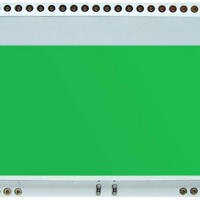
EA LED55X46-E ELECTRONIC ASSEMBLY, EA LED55X46-E Datasheet - Page 7

EA LED55X46-E
Manufacturer Part Number
EA LED55X46-E
Description
LCD Graphic Display Modules & Accessories Pure Green Backlight For DOG-M Series
Manufacturer
ELECTRONIC ASSEMBLY
Datasheet
1.EA_LED55X46-R.pdf
(8 pages)
Specifications of EA LED55X46-E
Pixel Density
128 x 64
Fluid Type
STN
Module Size (w X H X T)
55 mm x 46 mm x 2 mm
Viewing Area (w X H)
51 mm x 31 mm
Backlighting
Green
Background Color
Green
Operating Temperature Range
- 20 C to + 70 C
Interface
SPI
Display Mode
Transmissive
Lead Free Status / RoHS Status
Lead free / RoHS Compliant
ELECTRONIC ASSEMBLY reserves
the right to change specifications
without prior notice. Printing and
typographical
12:00 VIEWING ANGLE, TOP VIEW OPTION
If the display is read mostly from above (on the front of a laboratory power supply unit,
for example), the preferred angle of viewing can be set to 12 o’clock. This rotaties the
TOUCH PANEL EA TOUCH128-1 (OPTIONAL)
An analog touch panel is available as an accessory. It has a self-adhesive material on its rear surface and is simply stuck
onto the display. The connection is made by means of a 4-pin flexible cable for a ZIF connector (e.g. EA WF100-04S)
with a grid of 1.0 mm. Bending radius is defined with min. 5mm. For optimum readability we recommend that you use
a backlight with the display.
Interfacing to a processor can be either done by an external touch panel controller or with a controller that is featured
with analogue input. The touch panel is similar to a potentiometer: connecting
ZIF CONNECTOR EA WF100-04S
As an accessory for the touch panel we do
provide a ZIF connector (4 pins) with pitch
1.0mm (SMD type). This connector „bottom
side contact“ type.
errors
reserved.
display by 180°. A slightly different initialization setup is required
for this. Also keep in mind that the leftmost column (normally
numbered as 0) will now change to 4.
Command
(15) Common output mode select
(8) ADC set
a voltage of e.g. 3.3V to the pins
Top-Bottom makes it possible to read
out a voltage on pin Left or Right
which is linear to the Y-coordinate of
the pressed point. The X-coordinate
will result when the voltage will be
supplied to
measurement is done at Top or
Bottom.
The pinout of the connecting cable is
shown in the drawing.
Initialisation example top view
A0
0
0
D7
1
1
Left-Right and
D6
0
1
D5
1
0
D4
0
0
D3
0
1
D2
0
0
D1
0
0
D0
0
0
Specification
Top-Bottom
Left-Right
Voltage
Current
Linearity
Force
Contact Bounce
Op. Temperatur
Stor. Temperatur
Transmission
Life Time
$A0 ADC normal
$C8 Reverse COM63~COM0
Hex
EA DOGM128-6
Remark
Assembling for 12:00 (Top View)
Specification
alle dimensions are in mm
10000
min
120
580
-20
-20
45
75
3
5
5
max
300
900
+60
+70
1,5
12
25
65
10
85
Page 7
Cycles
Unit
mA
ms
°C
°C
Ω
Ω
%
%
V
g


