EA EDIP240B-7LWTP ELECTRONIC ASSEMBLY, EA EDIP240B-7LWTP Datasheet - Page 19
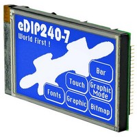
EA EDIP240B-7LWTP
Manufacturer Part Number
EA EDIP240B-7LWTP
Description
LCD Graphic Display Modules & Accessories Blue/White Contrast With Touch Screen
Manufacturer
ELECTRONIC ASSEMBLY
Datasheet
1.EA_EDIP240J-7LATP.pdf
(21 pages)
Specifications of EA EDIP240B-7LWTP
Pixel Density
240 x 128
Fluid Type
STN Negative
Module Size (w X H X T)
113 mm x 70 mm x 13 mm
Viewing Area (w X H)
91.18 mm x 56.3 mm
Backlighting
White
Background Color
Blue
Operating Temperature Range
- 20 C to + 70 C
Attached Touch Screen
Yes
Style
LCD Graphic Display
Interface
RS-232, I2C BUS, or SPI BUS
Lead Free Status / RoHS Status
Lead free / RoHS Compliant


MACRO PROGRAMMING
Single or multiple command sequences can be grouped together in macros and stored in the
EEPROM. You can then start them by using the Run macro commands. There are different types of
macro:
Normal macros (0 through 255)
These are started by means of an ‘ESC MN xx’ command via the serial interface or from another macro.
A series of macros occurring one after the other can be called cyclically (movie, hourglass, multi-page
help text). These automatic macros continue to be processed until a command is received via RS-232
or another macro is activated.
Furthermore these macros may be started by "macro processes" as an individual task (from V1.1).
Process macros will not be interupted by any other commands or touch panel use.
Touch macro (1 through 255)
Started when you touch/release a touch field (only in versions with a touch panel - TP) or issue an
‘ESC MT xx’ command.
Menu macro (1 through 255)
Started when you choose a menu item or issue an ‘ESC MM xx’ command.
Power-on macro
Started after power-on. You can switch off the cursor and define an opening screen, for example.
Reset macro
Started after an external reset or after a voltage dip under 4.7V (VDD-VSS).
Watchdog macro
Started after a fault/error (e.g. crash).
Brown-out macro
Started after a voltage dip <4V.
Important: If a continuous loop is programmed in the power-on, reset or watchdog macro, the display
can no longer be addressed. In this event, execution of the power-on macro must be suppressed. This
is achieved by wiring DPOM appropriately.
PowerOff - connect pin 13 (DPOM) to GND - PowerOn - disconnect pin 13 again.
WRITE PROTECTION FOR MACRO PROGRAMMING AND FONTS
A VDD line level at pin 19 (EEP_WP) prevents inadvertent overwriting of the macros, images and fonts
in the EEPROM (recommanded in any case!).
MEMORY EXPANSION
The size of the internal EEPROM memory is 32 kB. Generally, this allows sufficient space for a large
number of images and macros. If, however, a very large number of images (in particular full-size
images) are to be stored, it can be necessary to expand the memory. The memory capacity can be
doubled by directly connecting a standard EEPROM of the 24C256 series. It is connected over pins
17, 18 and 19 (I2C adress $A6) or can be placed direct as U12 (see drawing on page 20).
Specifications may be changed without
prior notice. Printing error reserved
EA eDIP240-7
Page 19
Related parts for EA EDIP240B-7LWTP
Image
Part Number
Description
Manufacturer
Datasheet
Request
R

Part Number:
Description:
LCD Graphic Display Modules & Accessories Starter/Demoboard w/Touch USB prog
Manufacturer:
ELECTRONIC ASSEMBLY
Datasheet:

Part Number:
Description:
Display Development Tools StrEval Kit Blk-Wht w/ Intf Exp and CD
Manufacturer:
ELECTRONIC ASSEMBLY
Datasheet:

Part Number:
Description:
Display Modules & Development Tools Starter/Demoboard Windows USB For DOGM
Manufacturer:
ELECTRONIC ASSEMBLY

Part Number:
Description:
Display Modules & Development Tools Starter/Demoboard DOGM/ Windows USB
Manufacturer:
ELECTRONIC ASSEMBLY
Datasheet:

Part Number:
Description:
LCD Character Display Modules 4x20 Yellow/Green RS-232 Interface
Manufacturer:
ELECTRONIC ASSEMBLY
Part Number:
Description:
LCD Character Display Modules 4x20 Blue-White RS-232 Interface
Manufacturer:
ELECTRONIC ASSEMBLY
Part Number:
Description:
LCD Character Display Modules 2x16 Yellow/Green RS-232 Interface
Manufacturer:
ELECTRONIC ASSEMBLY

Part Number:
Description:
LCD Character Display Modules STN(+) Reflective Yel/Grn Background
Manufacturer:
ELECTRONIC ASSEMBLY
Datasheet:

Part Number:
Description:
LCD Character Display Modules STN(-) Transmissive Blue Background
Manufacturer:
ELECTRONIC ASSEMBLY
Datasheet:

Part Number:
Description:
LCD Character Display Modules FSTN(-) Transmissive Black Background
Manufacturer:
ELECTRONIC ASSEMBLY
Datasheet:

Part Number:
Description:
LCD Touch Panels Touchpanel Analog for DOGM128-6
Manufacturer:
ELECTRONIC ASSEMBLY
Datasheet:
Part Number:
Description:
LCD Touch Panels Touchpanel Analog For DOGS102
Manufacturer:
ELECTRONIC ASSEMBLY
Datasheet:
Part Number:
Description:
LCD Touch Panels Touchpanel Analog For DOGXL160
Manufacturer:
ELECTRONIC ASSEMBLY
Datasheet:
Part Number:
Description:
LCD Touch Panels Touchpanel Analog For DOG-L128-6
Manufacturer:
ELECTRONIC ASSEMBLY
Datasheet:

Part Number:
Description:
LED Displays Bezel 017-xx Series 75.0x24.2/ 91.0x36.4
Manufacturer:
ELECTRONIC ASSEMBLY
Datasheet: