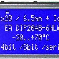
EA DIP204B-6NLW ELECTRONIC ASSEMBLY, EA DIP204B-6NLW Datasheet - Page 2

EA DIP204B-6NLW
Manufacturer Part Number
EA DIP204B-6NLW
Description
LCD Character Display Modules Black/White Contrast White LED Backlight
Manufacturer
ELECTRONIC ASSEMBLY
Datasheet
1.EA_DIP204B-6NLW.pdf
(4 pages)
Specifications of EA DIP204B-6NLW
Character Count X Line
20 x 4
Module Size (w X H X T)
75 mm x 46 mm x 11 mm
Background Color
Blue
Voltage Rating
3.3 V / 5 V
Operating Temperature Range
- 20 C to + 70 C
Backlight Type
LED Blue
Interface
4 Bit, 8 Bit, Serial SPI
Lead Free Status / RoHS Status
Lead free / RoHS Compliant
EA DIP204-6
Page 2
PINOUT
BACKLIGHT
Using the LED backlight requires an current source or external current-limiting resistor. Forward
voltage for white LED backlight is 3.0~3.6V. Please take care of derating for T
Attention: Do never drive backlight directly to 5V; this may damage backlight immediately !
The blue display cannot be read without backlight. For direct sunlight we suggest to use the J-type.
TABEL OF COMAND (KS0073, IE=HIGH)
Pin Symbol Function
10
11
12
1
2
3
4
5
6
7
8
9
Cursor At Home
Cursor / Display
Entry Mode Set
Display On/Off
Address Read
Scroll Enable
Clear Display
Power Down
Function Set
Function Set
Address Set
Address Set
Address Set
Busy Flag /
Write Data
Instruction
Read Data
Set Scroll
extended
SEG RAM
Quantity
CG RAM
DD RAM
Control
Mode
VDD
VSS
RES
R/W
VCI
Shift
RS
E
Power Supply 0V (GND)
Power Supply +5V
Contrast Adjustment
L: Reset
H=Data; L=Command
H=Read, L=Write
Enable
not connected
not connected
not connected
not connected
not connected
RE
Bit
0
1
0
0
0
1
0
1
0
1
0
1
0
1
*
*
*
*
RS
0
0
0
0
0
0
0
0
0
0
0
0
0
0
0
0
1
1
4-/8-Bit Mode (Factory Set)
R/W
0
0
0
0
0
0
0
0
0
0
0
0
0
0
0
1 BF
0
1
DB
7
0
0
0
0
0
0
0
0
0
0
0
0
0
1
1
DB
6
0
0
0
0
0
0
0
0
0
0
0
1
1
*
C ode
DB
5
0
0
0
0
0
0
0
0
0
1
1
*
Pin Symbol Function
Write Data
Read Data
13
14
15
16
17
18
19
20
21
22
23
24
DB
DL N RE DH
DL N RE BE LP
4
0
0
0
0
0
0
0
1
1
*
D4 (D0) Display Data D4
D5 (D1) Display Data D5
D6 (D2) Display Data D6
D7 (D3) Display Data, MSB
S/C R/L
DB
H4 H3 H2 H1
AC
AC
VSS
3
0
0
0
0
0
1
1 FW BW NW
D0
D1
D2
D3
A
C
SQ
AC
DB
2
0
0
0
1
1
D
AC
not connected
Power Supply 0V (GND)
Display Data, LSB
Display Data D1
Display Data D2
Display Data D3
LED-B/L + (ext. Resistor requ)
LED-B/L -
DB
I/D S
C
1
0
1
1 PD
1 BID
*
REV
DB
B
0
1
*
*
Clears all display and returns the cursor to the
home position (Address 0).
Returns the Cursor to the home position (Address
0). Also returns the display being shifted to the
original position. DD RAM contents remain
unchanged.
Set Power down mode bit.
PD=0: powerdown mode disable
PD=1: powerdown mode enable
Cursor moving direction (I/D=0: dec; I/D=1: inc)
shift enable bit (S=0: disable; S=1: enable shift)
Segment bidirectional function
(BID=0: Seg1->Seg60; BID=1: Seg60->Seg1)
D=0: display off; D=1: display on
C=0: cursor off; C=1: cursor on
B=0: blink off; B=1: blink on
FW=0: 5-dot font width; FW=1: 6-dot font width
BW=0: normal cursor; BW=1: inverting cursor
NW=0: 1- or 2-line (see N); NW=1: 4-line display
Moves the Cursor or shifts the display
S/C=0: cursor Shift; S/C=1: display shift
R/L=0: shift to left; R/L=1: shift to right
Determine the line for horizontal scroll
sets interface data length (DL=0:4-bit; DL=1:8-bit)
number of display lines (N=0: 1-line; N=1: 2-line)
extension register (RE= 0/1)
scroll/shift (DH=0: dot scroll; DH=1: display shift)
reverse bit (REV=0:normal; REV=1:inverse display)
CG-/SEG-RAM blink (BE=0: disable; BE=1:
enable)
LP=0: normal mode; LP=1: low power mode
Sets the CG RAM address. CG RAM data is sent
and received after this setting.
Sets the SEG RAM address. SEG RAM data is
sent and received after this setting.
Sets the DD RAM address. DD RAM data is sent
and received after this setting.
Sets the quantity of horizontal dot scroll (DH=0)
Reads Busy flag (BF) indicating internal operation
is being performed and reads address counter
contents.
Writes data into internal RAM
(DD RAM / CG RAM / SEGRAM)
Reads data from internal RAM
(DD RAM / CG RAM / SEGRAM)
Description
Pin Symbol Function
10
11
12
1
2
3
4
5
6
7
8
9
SCLK
VDD
VSS
RES
VCI
SID
CS
Power Supply 0V (GND)
Power Supply +5V
Contrast Adjustment
L: Reset
Chip Select
Data In
Shift Clock
not connected
not connected
not connected
not connected
not connected
SPI Mode (Solder link changed to "SPI")
Execute
(270kHz)
1.53ms
1.53ms
Time
39µs
39µs
39µs
39µs
39µs
39µs
39µs
39µs
39µs
39µs
39µs
39µs
39µs
43µs
43µs
-
ELECTRONIC ASSEMBLY reserves
the right to change specifications
without prior notice. Printing and
typographical
Pin Symbol Funktion
13
14
15
16
17
18
19
20
21
22
23
24
a
>+25°C
SOD
VSS
A
C
not connected
Power Supply 0V (GND)
Data Out
not connected
not connected
not connected
not connected
not connected
not connected
not connected
LED-B/L + (ext. Resistor requ)
LED-B/L -
errors
reserved.


