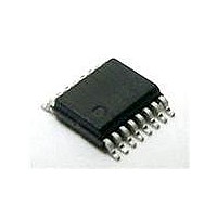
CM2006-02QR ON Semiconductor, CM2006-02QR Datasheet - Page 2

CM2006-02QR
Manufacturer Part Number
CM2006-02QR
Description
IC VGA PORT COMPANION 16QSOP
Manufacturer
ON Semiconductor
Series
Praetorian®r
Type
The CM2006 connects between the VGA or DVI-I port connector and the internal analog or digital flat panel controller logic.r
Specifications of CM2006-02QR
Applications
Monitors, TV
Voltage - Supply
5V
Package / Case
16-QSOP
Mounting Type
Surface Mount
Operating Supply Voltage
- 0.5 V to + 6 V
Supply Current
10 uA
Maximum Operating Temperature
+ 85 C
Minimum Operating Temperature
- 40 C
Mounting Style
SMD/SMT
Number Of Channels
7
Lead Free Status / RoHS Status
Lead free / RoHS Compliant
Interface
-
Lead Free Status / Rohs Status
Lead free / RoHS Compliant
Available stocks
Company
Part Number
Manufacturer
Quantity
Price
Part Number:
CM2006-02QR
Manufacturer:
CMD
Quantity:
20 000
Product Description (cont’d)
Two N-channel MOSFETs provide the level shifting
function required when the DDC controller or EDID
EEPROM is operated at a lower supply voltage than
the monitor. The gate terminals for these MOSFETS
© 2006 California Micro Devices Corp. All rights reserved.
2
Note: This drawing is not to scale.
LEAD(s)
10
11
12
13
14
15
16
1
2
3
4
5
6
7
8
9
490 N. McCarthy Blvd., Milpitas, CA 95035-5112
SYNC_OUT1
SYNC_OUT2
DDC_OUT1
DDC_OUT
SYNC_IN1
SYNC_IN2
DDC_IN1
DDC_IN2
VIDEO_1
VIDEO_2
VIDEO_3
V
ENABLE
NAME
CC_DDC
GND
BYP
V
CC
DESCRIPTION
This is a supply input for the SYNC_1 and SYNC_2 level shifters, video protection and the
DDC circuits.
Active high enable. Disables the Sync buffer outputs when low.
Video signal ESD protection channel. This pin is typically tied one of the video lines between
the controller device and the video connector.
Video signal ESD protection channel. This pin is typically tied one of the video lines between
the controller device and the video connector.
Video signal ESD protection channel. This pin is typically tied one of the video lines between
the controller device and the video connector.
Ground reference supply pin.
This is an isolated supply input for the DDC_1 and DDC_2 level-shifting N-FET gates.
An external 0.22uF bypass capacitor is required on this pin.
DDC signal input. Connects to the video connector side of one of the DDC lines.signal output.
DDC signal output. Connects to the monitor DDC logic.
DDC signal output. Connects to the monitor DDC logic.
DDC signal input. Connects to the video connector side of one of the DDC lines
Sync signal buffer input. Connects to the video connector side of one of the sync lines.
Sync signal buffer output. Connects to the monitor SYNC logic.
Sync signal buffer input. Connects to the video connector side of one of the sync lines.
Sync signal buffer output. Connects to the monitor SYNC logic.
VIDEO_1
VIDEO_2
VIDEO_3
V
ENABLE
CC_DDC
PACKAGE / PINOUT DIAGRAM
GND
BYP
V
CC
PIN DESCRIPTIONS
16 Pin QSOP
●
1
2
3
4
5
6
7
8
Top View
Tel: 408.263.3214
(V
cally 3.3V, 2.5V etc.) that supplies power to the trans-
ceivers of the DDC controller.
CC_DDC
16
15
14
13
12
11
10
9
) should be connected to the supply rail (typi-
●
SYNC_OUT2
SYNC_IN2
SYNC_OUT1
SYNC_IN1
DDC_IN2
DDC_OUT2
DDC_OUT1
DDC_IN1
Fax: 408.263.7846
PRELIMINARY
●
www.cmd.com
CM2006
02/21/06


