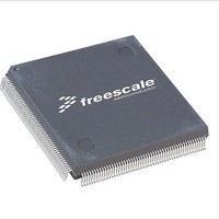
MCF51JE256CLL Freescale Semiconductor, MCF51JE256CLL Datasheet - Page 28

MCF51JE256CLL
Manufacturer Part Number
MCF51JE256CLL
Description
IC MCU 32BIT 256K FLASH 100LQFP
Manufacturer
Freescale Semiconductor
Series
MCF51JEr
Datasheet
1.TWR-MCF51JE.pdf
(50 pages)
Specifications of MCF51JE256CLL
Core Processor
Coldfire V1
Core Size
32-Bit
Speed
50MHz
Connectivity
CAN, EBI/EMI, I²C, SCI, SPI, USB OTG
Peripherals
LVD, PWM, WDT
Number Of I /o
65
Program Memory Size
256KB (256K x 8)
Program Memory Type
FLASH
Ram Size
32K x 8
Voltage - Supply (vcc/vdd)
1.8 V ~ 3.6 V
Data Converters
A/D 12x12b, D/A 1x12b
Oscillator Type
External
Operating Temperature
-40°C ~ 85°C
Package / Case
100-LQFP
Processor Series
MCF51JE
Core
ColdFire V1
Mounting Style
SMD/SMT
3rd Party Development Tools
JLINK-CF-BDM26, EWCF
Development Tools By Supplier
DEMOEM
Package
100LQFP
Device Core
ColdFire
Family Name
MCF51JE
Maximum Speed
50.33 MHz
Operating Supply Voltage
2.5|3.3 V
Data Bus Width
32 Bit
Number Of Programmable I/os
65
Interface Type
I2C/SCI/SPI
On-chip Adc
8-chx12-bit
On-chip Dac
1-chx12-bit
Number Of Timers
1
Lead Free Status / RoHS Status
Lead free / RoHS Compliant
Eeprom Size
-
Lead Free Status / Rohs Status
Details
Available stocks
Company
Part Number
Manufacturer
Quantity
Price
Company:
Part Number:
MCF51JE256CLL
Manufacturer:
Freescale Semiconductor
Quantity:
10 000
Preliminary Electrical Characteristics
1-2
10
11
12
13
14
15
16
#
1
2
3
4
5
6
7
8
9
Resolution
Supply current low-power mode
Supply current high-power mode
Full-scale Settling time
(±0.5 LSB)
(0x080 to 0xF7F or 0xF7F to 0x080)
low-power mode
Full-scale Settling time
(±0.5 LSB)
(0x080 to 0xF7F or 0xF7F to 0x080)
high-power mode
Code-to-code Settling time
(±0.5 LSB)
(0xBF8 to 0xC08 or 0xC08 to
0xBF8)
low-power mode
Code-to-code Settling time
(±0.5 LSB)
(0xBF8 to 0xC08 or 0xC08 to
0xBF8)
high-power mode
DAC output voltage range low
(high-power mode, no load, DAC
set to 0)
DAC output voltage range high
(high-power mode, no load, DAC
set to 0x0FFF)
Integral non-linearity error
Differential non-linearity error
VDACR is > 2.4 V
Offset error
Gain error
Power supply rejection ratio
V
Temperature drift of offset voltage
(DAC set to 0x0800)
Offset aging coefficient
DD
≥ 2.4 V
Characteristic
Figure 7. Offset at Half Scale vs Temperature
Table 14. DAC 12-Bit Operating Behaviors
Preliminary — Subject to Change
I
I
DDA_DACHP
DDA_DACLP
Ts
Ts
Symbol
Ts
V
Ts
V
PSRR
dacouth
DNL
dacoutl
C-C
C-C
INL
T
FS
E
E
FS
A
N
co
O
G
c
HP
LP
HP
LP
R
V
Min
120
-100
12
60
50
—
DAC
—
—
—
—
—
—
—
—
—
—
1(TBD)
(TBD)
(TBD)
(TBD)
(TBD)
(TBD)
± 0.5
± 0.5
Max
TBD
100
500
100
200
± 8
± 1
12
30
—
—
5
2
µV/yr
%FS
%FS
LSB
LSB
Unit
mV
mV
mV
µA
µA
dB
bit
µs
µs
µs
µs
R
R
C
C
C
C
C
C
C
C
C
C
C
C
C
C
C
C
C
Freescale Semiconductor
See Typical
Drift figure
that follows.
Notes


