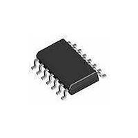
AT42QT1070-SSU Atmel, AT42QT1070-SSU Datasheet - Page 4

AT42QT1070-SSU
Manufacturer Part Number
AT42QT1070-SSU
Description
IC TOUCH SENSOR 7KEY 14-SOIC
Manufacturer
Atmel
Type
Capacitiver
Specifications of AT42QT1070-SSU
Number Of Inputs/keys
7 Key (Comms), 5 Key (Standalone)
Data Interface
I²C
Voltage Reference
Internal
Voltage - Supply
1.8 V ~ 5.5 V
Operating Temperature
-40°C ~ 85°C
Mounting Type
Surface Mount
Package / Case
14-SOIC (0.154", 3.90mm Width)
Supply Voltage
1.8 V to 5.5 V
Dimensions
3 mm L x 3 mm W x 0.8 mm H
Temperature Range
- 40 C to + 85 C
Termination Style
SMD/SMT
Lead Free Status / RoHS Status
Lead free / RoHS Compliant
Current - Supply
-
Resolution (bits)
-
Touch Panel Interface
-
Data Rate/sampling Rate (sps, Bps)
-
Lead Free Status / Rohs Status
Lead free / RoHS Compliant
Available stocks
Company
Part Number
Manufacturer
Quantity
Price
Company:
Part Number:
AT42QT1070-SSU
Manufacturer:
ATMEL
Quantity:
2 000
Company:
Part Number:
AT42QT1070-SSU QS529
Manufacturer:
Atmel
Quantity:
4 905
10620D–AT42–04/09
Table of Contents (Continued)
iv
Section 4
Mutual-capacitance Zero-dimensional Sensors ......................................................... 4-1
Section 5
Self-capacitance One-dimensional Sensors .............................................................. 5-1
4.1
4.2
4.3
5.1
5.2
5.3
Introduction ........................................................................................................................ 4-1
Planar Construction ........................................................................................................... 4-1
Non-Planar Construction.................................................................................................. 4-10
Introduction ........................................................................................................................ 5-1
General Advice .................................................................................................................. 5-1
Typical Spatially Interpolated Method ................................................................................ 5-3
3.3.2
3.3.3
3.3.4
3.3.5
3.3.6
3.3.7
4.2.1
4.2.2
4.2.3
4.2.4
4.2.5
4.2.6
4.2.7
4.2.8
4.3.1
4.3.2
4.3.3
4.3.4
4.3.5
4.3.6
4.3.7
4.3.8
5.2.1
5.2.2
5.2.3
5.2.4
5.2.5
5.3.1
5.3.2
Philipp Spring
Secondary Substrate Method ............................................................................ 3-10
Ground Loading ................................................................................................. 3-10
Illumination Effects............................................................................................. 3-10
Floating Conductive Items ................................................................................. 3-11
Conductive Paints.............................................................................................. 3-11
Introduction .......................................................................................................... 4-1
X and Y Electrodes .............................................................................................. 4-2
Ground Loading ................................................................................................... 4-6
Interconnection .................................................................................................... 4-7
Illumination Effects............................................................................................... 4-9
Floating Conductive Items ................................................................................... 4-9
Conductive Paints................................................................................................ 4-9
Transparent Y Electrodes .................................................................................... 4-9
Introduction ........................................................................................................ 4-10
Flooded-X Two-layer Method ............................................................................ 4-10
Spring Method ................................................................................................... 4-12
Adapting the Planar Construction For Distribution Across Two Layers ............. 4-13
Ground Loading ................................................................................................. 4-13
Illumination Effects............................................................................................. 4-13
Floating Conductive Items ................................................................................. 4-13
Conductive Paints.............................................................................................. 4-13
Ground Loading ................................................................................................... 5-1
Interconnection .................................................................................................... 5-1
Hand Shadow Effect ............................................................................................ 5-2
Floating Conductive Items ................................................................................... 5-2
Conductive Paints................................................................................................ 5-2
Introduction .......................................................................................................... 5-3
Small Slider Or Wheel ......................................................................................... 5-3
™
Method ....................................................................................... 3-8
Touch Sensors Design Guide


