98-0003-3222-5 3M, 98-0003-3222-5 Datasheet - Page 2
98-0003-3222-5
Manufacturer Part Number
98-0003-3222-5
Description
COMMAND ADHESIVE STRIPS 7.875"
Manufacturer
3M
Series
Command™r
Datasheet
1.98-0003-3222-5.pdf
(2 pages)
Specifications of 98-0003-3222-5
Tape Type
Double Coated, Double Sided
Adhesive
Rubber
Backing, Carrier
Crepe Paper
Width
0.625" (15.9mm) 5/8"
Length
7.87" (200mm)
Color
White
Usage
Touch Screens
Temperature Range
-40 ~ 158°F (-40 ~ 70°C)
For Use With
3M5754 - TOUCH SCREEN CAPACITIVE 12.31"3M5752 - TOUCH SCREEN CAPACITIVE 19.75"3M5750 - TOUCH SCREEN CAPACITIVE 20.65"3M5748 - TOUCH SCREEN CAPACITIVE 17.54"3M5747 - TOUCH SCREEN CAPACITIVE 6.71"3M5745 - TOUCH SCREEN CAPACITIVE 15.68"3M5744 - TOUCH SCREEN CAPACITIVE 10.83"3M5527 - TOUCH SCREEN CAPACITIVE 31.80"3M5526 - TOUCH SCREEN CAPACITIVE 20.65"3M5525 - TOUCH SCREEN CAPACITIVE 19.75"3M5524 - TOUCH SCREEN CAPACITIVE 17.54"3M5523 - TOUCH SCREEN CAPACITIVE 15.68"3M5522 - TOUCH SCREEN CAPACITIVE 12.31"3M5521 - TOUCH SCREEN CAPACITIVE 10.83"3M5520 - TOUCH SCREEN CAPACITIVE 8.75"3M5519 - TOUCH SCREEN CAPACITIVE 6.71"
Lead Free Status / RoHS Status
Lead free / RoHS Compliant
Thickness
-
Thickness - Adhesive
-
Thickness - Backing, Carrier, Liner
-
Lead Free Status / Rohs Status
Lead free / RoHS Compliant
Other names
3M9582


To begin, separate individual strips from the larger sheet.
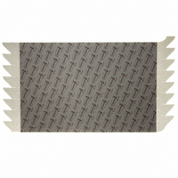
Place Command Strips around full perimeter of the display frame (figure 1)
starting in the four corners. Then fill in the remaining spaces with additional
Command Strips. (figure 2).
The Command Strips adhesive is the same on both sides so it makes no
difference which side is placed on the display frame.
The pull tabs must remain outside of the physical frame of the display
and away from the viewing area of the LCD, so the user can pull on the
tab to remove the strip if replacement is necessary.
Be sure to follow the guidelines specified in the 3M
ClearTek
corners to allow for venting.
Remove the release liner on the Command Strips to allow for placement
of the touch sensor. Place the touch sensor on top of the Command
Strips by carefully aligning the corners of the touch sensor to fit properly
with the corners of the LCD frame (figure 3).
3M Touch Systems
Subsidiary of 3M Company
501 Griffin Brook Park Drive
Methuen, MA 01844
U.S.A.
1-888-659-1080
www.3M.com/touch
1
Integrating a touch sensor
Command
Apply First Four Strips in Corners
™
II Integration Guide (19-278) requiring 1-3 mm gaps in the
3
Mount The Touch Sensor
™
Strips for Touch Sensors Quick Start Guide
NOTICE: Command
known as the 3M
their particular touch sensor and in their intended application.
IMPORTANT NOTICE TO PURCHASER: Specifications are subject to change without notice. These 3M Touch Systems’ Products and software are warranted to meet their published specifications
from the date of shipment and for the period stated in the specification. 3M Touch Systems makes no additional warranties, express or implied, including but not limited to any implied warranties of
merchantability or fitness for a particular purpose. User is responsible for determining whether the 3M Touch Systems Products and software are fit for User’s particular purpose and suitable for its
method of production, including intellectual property liability for User’s application. If the Product, software or software media is proven not to have met 3M Touch Systems’ warranty, then 3M Touch
Systems’ sole obligation and User’s and Purchaser’s exclusive remedy, will be, at 3M Touch Systems’ option, to repair or replace that Product quantity or software mediator to refund its purchase
price. 3M Touch Systems has no obligation under 3M Touch Systems’ warranty for any Product, software or software media that has been modified or damaged through misuse, accident, neglect,
or subsequent manufacturing operations or assemblies by anyone other than 3M Touch Systems. 3M Touch Systems shall not be liable in any action against it in any way related to the Products or
software for any loss or damages, whether non-specified direct, indirect, special, incidental or consequential (including downtime, loss of profits or goodwill) regardless of the legal theory asserted. (7/02)
3M and Command are trademarks of 3M Company.
2
™
Apply Next Four Strips
™
MicroTouch
Strips for Touch Sensors were developed for use with the 3M
™
MicroTouch
™
ClearTek
™
™
Printed in USA
II System). Customers must determine whether Command Strips are suitable for use with
Grab the Command Strips "pull tab" with forefinger and thumb (figure 4).
Pull straight out at a 90° angle from the sensor (figure 5), but in the same
plane as the Command Strip. Repeat this sequence until all the Command
Strips are removed. Lift off the touch sensor.
Do not rest your hand on the sensor while removing the Command Strips.
If the pull tab end breaks, simply use a utility knife or small screw driver
to pull out the broken end and pull the end.
© 3M 2009 All Rights Reserved.
4
5
Removing a touch sensor
Grab Pull Tab with Thumb and Forefinger
Pull Tab at 90 Degrees
™
MicroTouch
™
System SCT3250EX (previously
COMMAND-0409