S331 NKK Switches, S331 Datasheet - Page 7
S331
Manufacturer Part Number
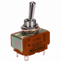
S331
Description
SWITCH TOGGLE DPST 25A SLDR 5PCS
Manufacturer
NKK Switches
Series
S300r
Type
Toggler
Specifications of S331
Circuit
DPST
Switch Function
On-Off
Contact Rating @ Voltage
25A @ 125VAC
Actuator Type
Standard Round
Actuator Length
17.50mm
Illumination
Non-Illuminated
Mounting Type
Panel Mount
Termination Style
Solder Lug
Bushing Thread
M12
Body Style
Standard
Contact Form
DPST
Current, Rating
25 A
Dielectric Strength
2000 VAC
Mounting Hole Size
0.492 "
Number Of Poles
2
Number Of Positions
2
Operation
On-None-Off
Special Features
Medium/High Capacity
Termination
Solder
Voltage, Rating
250/30 VAC/VDC
Pole Throw Configuration
DPST
Switch Configuration
ON None OFF
Actuator Style
Toggle
Current Rating (max)
25A
Ac Voltage Rating (max)
250VVAC
Dc Voltage Rating (max)
30VVDC
Contact Material
Silver Alloy/Copper
Contact Plating
Silver
Mechanical Life
50000
Product Height (mm)
54.6mm
Product Depth (mm)
19mm
Operating Temperature Min Deg. C
-10C
Product Length (mm)
33.2mm
Operating Temperature Max Deg. C
70C
Mounting Style
Panel
Lead Free Status / RoHS Status
Lead free / RoHS Compliant
Other names
360-1191
360-1191
360-2087
S331-RO
360-1191
360-2087
S331-RO
Available stocks
Company
Part Number
Manufacturer
Quantity
Price

Part Number:
S331
Manufacturer:
N/A
Quantity:
20 000
Part Number:
S3310
Manufacturer:
SEM
Quantity:
20 000
Part Number:
S3311
Manufacturer:
SEM
Quantity:
20 000
Company:
Part Number:
S331K25X5FN63J5R
Manufacturer:
VISHAY
Quantity:
30 000
Company:
Part Number:
S331K25X7RN63J5R
Manufacturer:
VISHAY
Quantity:
30 000
Company:
Part Number:
S331K25X7RP63K5R
Manufacturer:
VISHAY
Quantity:
30 000
Company:
Part Number:
S331K25Y5PN63J5R
Manufacturer:
VISHAY
Quantity:
30 000
Company:
Part Number:
S331K25Y5PP63K5R
Manufacturer:
VISHAY
Quantity:
30 000


A
Series S
A108
General Specs. page for approval marks
General Specs. page for approval marks
Flatted Lever
Notes: Standard Hardware: AT503M Face Hex Nut, AT506M Locking Ring, AT508 Lockwasher, AT527M Backup Hex Nut. See Accessories & Hardware section.
Optional Splashproof Boot Assemblies: AT401 & AT4181 boots plus hex nut & o-ring. See Accessories & Hardware section.
*
S41/S41R
S42/S42R
S43/S43R
S48/S48R
S49/S49R
Notes: Standard Hardware for Bat Lever: AT503M Face Hex Nut, AT506M Locking Ring, AT508 Lockwasher, AT527M Backup Hex Nut;
for Flatted Lever (R): AT504M Knurled Face Nut, AT508 Lockwasher, AT527M Backup Hex Nut. See Accessories & Hardware section.
Optional Splashproof Boot Assemblies (only for bat lever models): AT401 & AT4181 boots plus hex nut and o-ring. See Accessories & Hardware section.
*
Throw &
Schematics:
*See Supplement section for UL detail &
S45
Throw &
Schematics:
*See Supplement section for UL detail &
Suffix R =
Model
Wire harness & cable assemblies offered only in Americas.
Model
Wire harness & cable assemblies offered only in Americas.
S31
S32
S33
S35
S38
S39
S42R
S32
–
R
4PST
R
*Approvals
*Approvals
1
3PST
C
C
Bat lever dimensions are same as on S30 models above.
US
1
US
Keyway
Keyway
––
––
––
3
4
Pole &
.354
(30.0)
Throw
Pole &
Throw
(9.0)
1.181
4PDT
4PDT
4PDT
4PDT
4PDT
4PST
3PDT
3PDT
3PDT
3PDT
3PDT
3PST
3
4
6
(ON) 2-3 5-6 8-9 11-12
(ON)
ON 1-3 4-6 7-9 10-12
ON 2-3 5-6 8-9 11-12
ON 2-3 5-6 8-9 11-12
ON 2-3 5-6 8-9 11-12
ON 2-3 5-6 8-9 11-12
ON
ON
ON
ON
ON
7
6
THREE POLE WITH SOLDER LUG
FOUR POLE WITH SOLDER LUG
α
(4.0)
.157
Keyway
7
.240
Down
1-3 4-6 7-9
2-3 5-6 8-9
2-3 5-6 8-9
2-3 5-6 8-9
2-3 5-6 8-9
2-3 5-6 8-9
(6.1) Dia
Keyway
Toggle Position/Connected Terminals
α
Down
9
10
Toggle Position/Connected Terminals
(8.15)
.321
(27.0)
1.063
9
(17.5)
.689
www.nkk.com
M12 P1
( ) = Momentary
INTERNAL
CONNECTION
M12 P1
12
( ) = Momentary
Center
NONE
NONE
NONE
Medium/High Capacity Standard Size Toggles
(12.0)
.472
OFF
OFF
OFF
INTERNAL
CONNECTION
(12.0)
.472
NONE
NONE
NONE
Center
OFF
OFF
OFF
(ON)
(ON)
(ON)
OFF
ON
ON
S41 and S41R do not have terminals 2, 5, 8, & 11.
(27.3)
1.075
1.067
(27.1)
3PDT
4PDT
(ON) 2-1 5-4 8-7 11-10
(ON) 2-1 5-4 8-7 11-10
(ON) 2-1 5-4 8-7 11-10
OFF
ON
ON
3
.228
(5.8)
2-1 5-4 8-7
2-1 5-4 8-7
2-1 5-4 8-7
2-1 5-4 8-7
2-1 5-4 8-7
(5.0)
.197
Up
3
.094
2-1 5-4 8-7 11-10
2-1 5-4 8-7 11-10
(2.4) Dia Typ
.094
(2.4) Dia Typ
2
(0.8) Typ
.031
(0.8) Typ
.031
(4.8) Typ
.189
(4.8) Typ
.189
1
2
—
Up
1
6
5
6
*
12
11
10
*
5
125V
25A
25A
25A
15A
15A
15A
4
AC
(COM)
—
9
8
7
terminals 2, 5, & 8
S31 does not have
9
8
7
4
(COM)
9
(36.5)
1.437
Resistive
9
Electrical Capacity
125V
25A
25A
25A
15A
15A
15A
250V
AC
9A
9A
9A
6A
6A
6A
8
AC
6
5
4
6
5
4
7
Electrical Capacity
Resistive
8
250V
12
3
2
1
7
9A
9A
9A
6A
6A
6A
AC
3
2
1
11
20A
20A
20A
20A
15A
15A
(34.2)
1.346
30V
DC
(33.8)
1.331
20A
20A
20A
20A
20A
20A
30V
Note: Terminal numbers
DC
10
Max. Panel Thickness:
Max. Panel Thickness:
Inductive
AC 125V
Panel Thickness:
Note: Terminal
.181” (4.6mm)
PF 0.6
AC 125V
Inductive
10A
10A
10A
.220” (5.6mm)
.181” (4.6mm)
8A
8A
8A
PF 0.6
are on the switch
Maximum
10A
10A
10A
8A
8A
8A
numbers are
on the switch
.060
(1.5)
(3.0) Dia
.118
(3.0) Dia
.118
(12.5) Dia
.492
.354
(12.5) Dia
.492
of Throw
(9.0)
of Throw
(12.5) Dia
.492
(11.5)
.453
.354
(9.0)
Angle
Angle
25°
25°
30°
25°
25°
25°
α =
25°
25°
30°
25°
25°
25°
α =
Related parts for S331
Image
Part Number
Description
Manufacturer
Datasheet
Request
R

Part Number:
Description:
Toggle Switches DPST ON-OFF MED/HIGH
Manufacturer:
NKK Switches
Datasheet:
Part Number:
Description:
Toggle Switches DPST ON-OFF SOLDER LUG 25A W/CSA MARK
Manufacturer:
NKK Switches
Datasheet:

Part Number:
Description:
SW TOGGLE DPST 25A
Manufacturer:
NKK Switches
Datasheet:

Part Number:
Description:
Toggle Switches 3PDT ON-OFF-ON 25A
Manufacturer:
NKK Switches
Datasheet:
Part Number:
Description:
Toggle Switches 3PDT ON-OFF-ON SOLDER LUG 25A W/UL
Manufacturer:
NKK Switches
Datasheet:
Part Number:
Description:
SWITCH TOGGLE 3PDT SOLDER LUG UL
Manufacturer:
NKK Switches
Datasheet:

Part Number:
Description:
SWITCH TOGGLE 3PDT 25A SLDR 5PCS
Manufacturer:
NKK Switches
Datasheet:

Part Number:
Description:
Rocker Switches & Paddle Switches High In-rush Rated Rocker Switch
Manufacturer:
NKK Switches
Datasheet:
Part Number:
Description:
Rocker Switches & Paddle Switches High In-rush Rated Rocker Switch
Manufacturer:
NKK Switches
Datasheet:
Part Number:
Description:
Rocker Switches & Paddle Switches High In-rush Rated Rocker Switch
Manufacturer:
NKK Switches
Datasheet:
Part Number:
Description:
Rocker Switches & Paddle Switches High In-rush Rated Rocker Switch
Manufacturer:
NKK Switches
Datasheet:

Part Number:
Description:
Pushbutton Switches SPST ON(OFF) 15/32'
Manufacturer:
NKK Switches
Datasheet:

Part Number:
Description:
Pushbutton Switches SPST OFF(ON) 15/32'
Manufacturer:
NKK Switches
Datasheet:

Part Number:
Description:
Pushbutton Switches ON(OFF) NORM CLSD 3A RED PLNGR LUG 15/32
Manufacturer:
NKK Switches
Datasheet:
Part Number:
Description:
Pushbutton Switches SPDT ON-(ON)
Manufacturer:
NKK Switches
Datasheet: