JF15RP3GF NKK Switches, JF15RP3GF Datasheet - Page 2
JF15RP3GF
Manufacturer Part Number
JF15RP3GF
Description
SW TACT SPST ILL BLU/GRN STR PCB
Manufacturer
NKK Switches
Series
JFr
Datasheet
1.JF15AP1CC.pdf
(6 pages)
Specifications of JF15RP3GF
Circuit
SPST-NO
Switch Function
Off-Mom
Contact Rating @ Voltage
0.05A @ 24VDC
Actuator Type
Square Button
Mounting Type
Through Hole
Orientation
Vertical
Outline
22.80mm x 17.70mm
Illumination
Illuminated
Operating Force
200gf
Actuator
Sculptured
Contact Current Rating
50 mAmps at 24 VoltsDC
Ground Terminal
No
Contact Form
SPST
Termination Style
Straight PC
Mounting Direction
Straight
Body Size
22.8 mm L x 17.7 mm W x 5.7 mm H
Features
Extremely low profile of 5 mm from PCB to top of switch with Green LED, spot illumination
Mounting Style
Through Hole
Operating Temperature Range
- 25 C to + 70 C
Travel
0.8 mm
Contact Rating
50 mAmps at 24 VoltsDC
Lead Free Status / RoHS Status
Lead free / RoHS Compliant


Distinctive
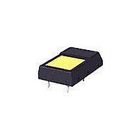
Extremely low profile of .224” (5.7mm) from PCB to top of switch.
Red, green, or yellow LED with spot or full face illumination.
Rubber seal construction prevents contact contamination
and allows automated soldering and cleaning.
Minimal operating force and short stroke
permit light touch operation.
Dome contact gives crisp tactile and
audible feedback to positively indicate
circuit transfer and assures high reliability
and long life.
Space saving body dimensions provide for compact,
side-by-side mounting on a standard grid.
Crimped terminals ensure secure mounting and prevent
dislodging during wave soldering.
Terminal spacing conforms to standard .100” (2.54mm) PCB grid.
Matching indicator available and shown at the end of Section M.
Illuminated Ultra-Thin Process Sealed Tactiles
4
3
1
These single pole, single throw switches can be used in a key-
board matrix and, using strapped terminals, achieve a com-
mon bus electrical configuration on a single-sided PC board.
4
1
7
A
5
2
2
5
8
0
9
7
Common Bus Matrix
3
9
B
6
13
10
12
11
6
8
Characteristics
3
4
5
6
8
9
0
A
B
1
2
7
1 2 3 4 5 6 7 8 9 10 11 12 13
P C T e r m i n a t i o n s
Red = PCB Trace
= ON
Black = Switch Circuit
www.nkk.com
5
These single pole, single throw switches can be
arranged on a single-sided PC board matrix
with strapped terminals to achieve an X-Y type
electrical interconnection.
1
4
7
A
4
2
5
8
0
3
X-Y Matrix
B
3
6
9
2
6
7
1
Series JF
Actual Size
PC Ter m i na t i ons
2
3
4
5
6
7
8
9
0
A
B
1
1 2 3 4 5 6 7
= ON
J41
J
Related parts for JF15RP3GF
Image
Part Number
Description
Manufacturer
Datasheet
Request
R

Part Number:
Description:
Rocker Switches & Paddle Switches High In-rush Rated Rocker Switch
Manufacturer:
NKK Switches
Datasheet:
Part Number:
Description:
Rocker Switches & Paddle Switches High In-rush Rated Rocker Switch
Manufacturer:
NKK Switches
Datasheet:
Part Number:
Description:
Rocker Switches & Paddle Switches High In-rush Rated Rocker Switch
Manufacturer:
NKK Switches
Datasheet:
Part Number:
Description:
Rocker Switches & Paddle Switches High In-rush Rated Rocker Switch
Manufacturer:
NKK Switches
Datasheet:

Part Number:
Description:
Pushbutton Switches SPST ON(OFF) 15/32'
Manufacturer:
NKK Switches
Datasheet:

Part Number:
Description:
Pushbutton Switches SPST OFF(ON) 15/32'
Manufacturer:
NKK Switches
Datasheet:

Part Number:
Description:
Pushbutton Switches ON(OFF) NORM CLSD 3A RED PLNGR LUG 15/32
Manufacturer:
NKK Switches
Datasheet:

Part Number:
Description:
Pushbutton Switches SPDT ON-(ON)
Manufacturer:
NKK Switches
Datasheet:

Part Number:
Description:
Pushbutton Switches ON-(ON) RND BUSH MNT RED LED RED/RED CAP
Manufacturer:
NKK Switches
Datasheet:
Part Number:
Description:
Pushbutton Switches SPST ON-(OFF) STRT
Manufacturer:
NKK Switches
Datasheet:
Part Number:
Description:
Pushbutton Switches OFF(ON) NORM OPEN 3A RED CAP LUG 15/32
Manufacturer:
NKK Switches
Datasheet:
Part Number:
Description:
Pushbutton Switches ILLUM PUSHBUTTON SPDT
Manufacturer:
NKK Switches
Datasheet:
Part Number:
Description:
Pushbutton Switches OFF(ON) NORM OPEN 3A BLK CAP LUG 15/32
Manufacturer:
NKK Switches
Datasheet:
Part Number:
Description:
Pushbutton Switches SPST NO Metric Thrd Blk Plunge w/Blu Cap
Manufacturer:
NKK Switches
Datasheet:
Part Number:
Description:
Pushbutton Switches SPST OFF-(ON) NO 3A
Manufacturer:
NKK Switches
Datasheet: