KSC241GLFS C&K Components, KSC241GLFS Datasheet - Page 3
KSC241GLFS
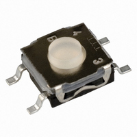
Manufacturer Part Number
KSC241GLFS
Description
SWITCH TACT SILVR 300GF GULLWING
Manufacturer
C&K Components
Series
KSCr
Datasheet
1.KSC141GLFS.pdf
(7 pages)
Specifications of KSC241GLFS
Circuit
SPST-NO
Switch Function
Off-Mom
Contact Rating @ Voltage
0.05A @ 32VDC
Actuator Type
Standard
Mounting Type
Surface Mount
Orientation
Vertical
Outline
6.20mm x 6.20mm
Illumination
Non-Illuminated
Operating Force
300gf
Pole Throw Configuration
SPST
Switch Function Configuration
N.O.
Actuator Style
Round Button
Actuator Length (mm)
0.9mm
Current Rating (max)
0.05A
Voltage Rating (vdc)
32V
Mechanical Life
300000
Contact Material
Silver
Product Length (mm)
6.2mm
Product Depth (mm)
10mm
Product Height (mm)
3.5mm
Operating Temp Range
-40C to 85C
Body Orientation
Straight
Mounting Style
Surface Mount
Terminal Type
Gull Wing
Lead Free Status / RoHS Status
Lead free / RoHS Compliant
Other names
401-1761-2
Available stocks
Company
Part Number
Manufacturer
Quantity
Price

Part Number:
KSC241GLFS
Manufacturer:
C&K进口
Quantity:
20 000


Summary
1.
2.
3.
4.
5.
6.
Annex 1: P/N affected by the change.................................................................................................... 11
Annex 2: Qualification plan.................................................................................................................... 17
Annex 3: Test report (abstract).............................................................................................................. 22
Annex 4: Test report (abstract).............................................................................................................. 35
Fig. 1 view with current central contact ................................................................................................... 4
Fig. 2 view with anti-particle central contact............................................................................................ 4
Fig. 3 Comparative view of old design (above) and new one (below)..................................................... 5
Fig. 4 standard contact with particle........................................................................................................ 5
Fig. 5 anti-particle contact with particle ................................................................................................... 6
Fig. 6 Dust proof test results.................................................................................................................... 6
Fig. 7 Plastic burr test results .................................................................................................................. 7
Fig. 8 Mix test results for standard contact.............................................................................................. 7
Fig. 9 Mix test results for standard contact.............................................................................................. 8
C&K
C&K components SAS - 1 rue Louis de la Verne B.P. 359 F-39105 Dole Cedex - FRANCE
Telephone :+33 (0)3 84 72 94 03 - Facsimile: +33 (0)3 84 79 20 39 – www.ck-components.com
Document subject to change without prior notice
Diffusion: no restriction
PCN07-09-KSC Rev.A – 14/11/07
2.1
2.2
2.3
2.4
4.1
4.2
4.3
4.4
4.5
Purpose........................................................................................................................................... 4
Change definition ............................................................................................................................ 4
Change impact and qualification method ....................................................................................... 8
Application ...................................................................................................................................... 9
Acknowledgement......................................................................................................................... 10
Support ......................................................................................................................................... 10
components
Overview ................................................................................................................................ 4
Illustration ............................................................................................................................... 4
New molding parameters ....................................................................................................... 5
Anti –particle contact analysis................................................................................................ 5
Overview ................................................................................................................................ 9
Product range affected........................................................................................................... 9
Date of application & time frame............................................................................................ 9
Ordering, pricing and stock handling policy ........................................................................... 9
Customer qualification............................................................................................................ 9
Product change notification
Page 3/35
Related parts for KSC241GLFS
Image
Part Number
Description
Manufacturer
Datasheet
Request
R

Part Number:
Description:
SWITCH TACT SILVER PLT GULLWING
Manufacturer:
C&K Components
Datasheet:

Part Number:
Description:
Tactile & Jog Switches Sealed SMT Tactile Switch
Manufacturer:
C&K Components

Part Number:
Description:
Rotary Switches 4P 3 POS ROTARY SW
Manufacturer:
C&K Components
Part Number:
Description:
ANALOG ROCKER C&K DELTATECH
Manufacturer:
C&K Components
Part Number:
Description:
QUARDANT MODUL C&K DELTATECH
Manufacturer:
C&K Components
Datasheet:
Part Number:
Description:
TOGGLE,THT-PC,SPDT,ON-OFF-ON,ACT-DXL:6.09X17.15MM,BUSH-THREADED,AU
Manufacturer:
C&K Components
Part Number:
Description:
SMARTCARD CONNECTOR *Y1112-2013AP LFT
Manufacturer:
C&K Components