B3W-9000-RG2N Omron, B3W-9000-RG2N Datasheet - Page 4
B3W-9000-RG2N
Manufacturer Part Number
B3W-9000-RG2N
Description
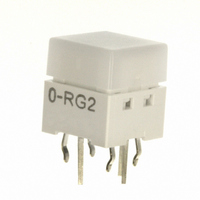
SWITCH TACT ILLM SPST-NO RED/GRN
Manufacturer
Omron
Series
B3W-9r
Specifications of B3W-9000-RG2N
Circuit
SPST-NO
Switch Function
Off-Mom
Contact Rating @ Voltage
0.05A @ 24VDC
Actuator Type
Square Button
Mounting Type
Through Hole
Orientation
Vertical
Outline
10.00mm x 10.00mm
Illumination
Illuminated
Operating Force
160gf
Actuator
Square
Termination Style
Pin
Body Size
10 mm L x 10 mm W x 11 mm H
Color
Milky White
Operating Temperature Range
- 25 C to + 70 C
Contact Configuration
SPST-NO
Contact Voltage Dc Nom
24V
Contact Current Max
50mA
Actuation Type
Top
Switch Terminals
Through Hole
Circuitry
SPST-NO
Rohs Compliant
Yes
Actuator / Cap Color
White
Lead Free Status / RoHS Status
Lead free / RoHS Compliant
Lead Free Status / RoHS Status
Lead free / RoHS Compliant, Lead free / RoHS Compliant
Other names
B3W-9000-RG2N
B3W9000RG2N
SW1038
B3W9000RG2N
SW1038
Available stocks
Company
Part Number
Manufacturer
Quantity
Price


B3W-9
LED Specifications
Note:
LEDs
■
■
Note:
4
Maximum operating current I
Recommended operating current I
Forward voltage (standard value) V
Maximum reverse voltage V
Ambient operating temperature
Forward current reduction curve
Forward current and forward voltage curves
300.0
200.0
100.0
10.0
50.0
20.0
100
5.0
2.0
1.0
0.5
0.2
0.1
50
40
30
20
10
80
60
40
20
0
0
0
0
0
1.0
0
For Switches with two LEDs, red and green, the recommended operating current is 12 mA for the red and 20 mA for the green LED
for application with three-color illumination.
1. Make sure that the polarity of the LEDs is correct. The polarity is not indicated on the Switch, but the positive pole is located on
2. Connect limiting resistors to the LEDs. The Switch does not have built-in limiting resistors, so satisfy the LED characteristics by
0.5
the back surface of the Switch on the side with the OMRON mark.
obtaining the limiting resistance according to the following formula based on the voltage to be used.
LED color
1.5
20
Red
1
Yellow
High brightness
Green and Blue
1.5
Red, Green
40
2.0
Ambient temperature Ta ( ° C)
2
Forward voltage V
Forward voltage V
R
FM
2.5
2.5
60
F
F
3
Yellow
F
F
27 mA
20 mA
1.8 V
5 V
−25°C to 70°C
80
(V)
3.5
3.0
(V)
Red
Limiting resistance (R)=
27 mA
20 mA
2.1 V
5 V
Green
100
35
30
25
20
15
10
90
80
70
60
50
40
30
20
10
5
0
0
0
(Voltage used (E) – LED forward voltage (VF))
0
0.5
R
Green (High brightness), Blue
1
LED forward current (IF)
E
1
27 mA
10 mA
3.7 V
5 V
Green (high brightness)
I
V
F
2
F
1.5
Green
2
3
Forward voltage V
Forward voltage V
2.5
4
3
F
F
(V)
(V)
3.5
5
(Ambient temperature Ta = 25°C)
45 mA
20 mA
2.4 V
5 V
( Ω )
Yellow
27 mA
10 mA
3.7 V
5 V
Blue
B3W-9
Related parts for B3W-9000-RG2N
Image
Part Number
Description
Manufacturer
Datasheet
Request
R

Part Number:
Description:
SWITCH TACT ILLUM SPST-NO GREEN
Manufacturer:
Omron
Datasheet:

Part Number:
Description:
SWITCH TACT ILLUM SPST-NO RED
Manufacturer:
Omron
Datasheet:

Part Number:
Description:
SWITCH TACT ILLUM SPST-NO BLUE
Manufacturer:
Omron
Datasheet:

Part Number:
Description:
SWITCH TACT ILLUM SPST-NO BLUE
Manufacturer:
Omron
Datasheet:

Part Number:
Description:
SWITCH TACT ILLUM SPST-NO YELLOW
Manufacturer:
Omron
Datasheet:

Part Number:
Description:
SWITCH TACT ILLUM SPST-NO YELLOW
Manufacturer:
Omron
Datasheet:

Part Number:
Description:
SWITCH TACT ILLUM SPST-NO GREEN
Manufacturer:
Omron
Datasheet:

Part Number:
Description:
SWITCH TACT ILLUM SPST-NO RED
Manufacturer:
Omron
Datasheet:

Part Number:
Description:
SWITCH TACT ILLUM SPST-NO GREEN
Manufacturer:
Omron
Datasheet:
Part Number:
Description:
SWITCH TACT ILLUM SPST-NO RED
Manufacturer:
Omron
Datasheet:

Part Number:
Description:
Keyswitch
Manufacturer:
Omron
Datasheet:

Part Number:
Description:
Keyswitch
Manufacturer:
Omron
Datasheet:

Part Number:
Description:
Pushbutton Switch,STRAIGHT,SPST,OFF-(ON),PC TAIL W/RETNN Terminal,PCB Hole Count:5
Manufacturer:
Omron
Datasheet:

Part Number:
Description:
Pushbutton Switch,STRAIGHT,SPST,OFF-(ON),PC TAIL W/RETNN Terminal,PCB Hole Count:5
Manufacturer:
Omron
Datasheet:

Part Number:
Description:
Pushbutton Switch,STRAIGHT,SPST,OFF-(ON),PC TAIL W/RETNN Terminal,PCB Hole Count:5
Manufacturer:
Omron
Datasheet: