B3F-4155 Omron, B3F-4155 Datasheet
B3F-4155
Specifications of B3F-4155
B3F4155
SW967


Related parts for B3F-4155


B3F-4155 Summary of contents
Page 1
... B3F-1102 B3F-1005 B3F-1105 B3F-1006 (See note.) --- B3F-1020 B3F-1120 B3F-1022 B3F-1122 B3F-1025 B3F-1125 B3F-1026 (See note.) --- --- B3F-1110 B3F-1060 (See note.) --- B3F-1062 (See note.) --- B3F-1070 (See note.) --- B3F-1072-N --- (See note.) B3F-1075 (See note.) --- B3F-1050 B3F-1150 B3F-1052 B3F-1152 B3F-1055 B3F-1155 B3F-1056 (See note.) --- ...
Page 2
... B3F-3150 --- B3F-3152 --- B3F-3155 Bags (100 Switches) Without ground With ground terminal terminal B3F-4000 B3F-4100 B3F-4005 B3F-4105 B3F-4050 B3F-4150 B3F-4055 B3F-4155 B3F-5000 B3F-5100 B3F-5050 B3F-5150 B3F-5001 B3F-5101 B3F-5051 B3F-5151 Operating force: 1.47 N {150 gf} Without ground With ground terminal terminal B3F-6002 B3F-6102 B3F-6022 ...
Page 3
... N) (B3F-1070: 500,000 operations min) 300,000 operations min (OF: 1.47 N) 100,000 operations min (OF: 2.55 N) 50,000 operations min (OF: 4.9 N) 3,000,000 operations min (OF: 1.28 N) 1,000,000 operations min (OF: 2.55 N) 10,000,000 operations min. B3F-1000, B3F-3000, B3F-6000 1 ...
Page 4
... PCB Mounting (Top View) (Single-sided PCB, t=1.6) 3.5 dia. Terminal Arrangement * /Internal Connections (Top View) * The height of B3F-1020, B3F-1022, B3F-1025, and B3F-1026 is 5±0.2 mm. Horizontal, Flat Plunger Type (with Ground Terminal, Pitch: 7.5 mm) B3F-1110 PCB Mounting (Top View) (Single-sided PCB, t=1.6) 3 ...
Page 5
... Vertical, Flat Plunger Type B3F-3100, B3F-3102, B3F-3105 3.5 dia. Five, 1±0.05 dia. Vertical, Projected Plunger Type B3F-3150, B3F-3152, B3F-3155 Two, 1.5±0.05 dia. 3.5 dia. Two, 1±0.05 dia. 2.4×2.4±0.1 B3F PCB Mounting (Top View) (Single-sided PCB, t=1.6) Four, 1±0.05 dia. ...
Page 6
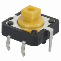
... Ground Terminal) B3F-4100, B3F-4105, B3F-5100, B3F-5101 Two, 1.8±0.05 dia. (For positioning boss) Four, 1.2±0.05 dia. Projected Plunger Type (with Ground Terminal) B3F-4150, B3F-4155, B3F-5150, B3F-5151 Two, 1.8±0.05 dia. (For positioning boss) Four, 3.8×3.8±0.1 1.2±0.05 dia. B3F PCB Mounting (Top View) (Single-sided PCB, t=1 ...
Page 7
... Ground Terminal) B3F-6100, B3F-6102 PCB Mounting (Top View) (Single-sided PCB, t=1.6) +0.1 Three, 1 dia. −0 Flat Plunger Type (without Ground Terminal) B3F-6020, B3F-6022 6±0.3 3.5 dia. 0.6 PCB Mounting (Top View) (Single-sided PCB, t=1.6) +0.1 Two, 1 −0 Note: The tape is random between surface A and surface B ...
Page 8
... View) (Single-sided PCB, t=1.6) +0.1 Two, 1 dia. −0 Note: The tape is random between surface A and surface B. Projected Plunger Type (with Ground Terminal) B3F-6150, B3F-6152 PCB Mounting (Top View) (Single-sided PCB, t=1.6) +0.1 Three, 1 dia. −0 Key Tops B32-series Special Key Tops are available for projected plunger models. Refer to page 42 for details. ...
Page 9
... B3F ALL DIMENSIONS SHOWN ARE IN MILLIMETERS. To convert millimeters into inches, multiply by 0.03937. To convert grams into ounces, multiply by 0.03527. Cat. No. A070-E1-05 16 B3F ...
Page 10
... Projected-plunger-type B3F, B3FS, and B3W Switches ■ Available in a wide range of colors and sizes. RoHS Compliant (Refer to page 8 for details.) Ordering Information For B3F, B3FS, and B3W Switches 6 × Switches Color (B3F-1000, B3F-3000, B3F-6000, B3W-1000, B3FS) 4 × Key Top Light gray B32-1000 ...
Page 11
B32 Dimensions All units are in millimeters unless otherwise indicated. Unless otherwise specified, a tolerance of ± 0.4 mm applies to all dimensions. Note: B32-10@0 R0.2 5.5 1.6 R0.5 4 2.5 ±0.15 2.3 2.5 4 ±0.15 B32-2000 B32-2010 R0.2 5.5 ...
Page 12
B32 B32-13@0 5.5 1.8 dia. 12 ±0.15 3.5 3.8 ±0.1 12 ±0.15 B32-16@0 7 3.55 3.8 ±0.1 ALL DIMENSIONS SHOWN ARE IN MILLIMETERS. To convert millimeters into inches, multiply by 0.03937. To convert grams into ounces, multiply by 0.03527. Cat. ...
Page 13
... Do not solder the Switch more than twice, including rectification soldering. An interval of five minutes is required between the first and second soldering. 2. Automatic Soldering Baths (B3F, B3W, B3WN, B3M, B3J) Soldering temperature: 260 ° C max. Soldering time max. for a 1.6-mm thick single-side PCB Preheating temperature: 100° ...
Page 14
... Switches in locations with high temperature or high humidity may result in deterioration of the tape and Switches, and long-term storage under such conditions may cause discoloration of the Switch terminals. 2. Packaging Specifications for Embossed Taping (B3FS-1000P/-1002P, B3SN) (18) Label Tape drawing direction 13 dia. 380±2 dia. ...
Page 15
... Precautions B3FS-1050P (22) Label Tape drawing direction 13 dia. 380±2 dia. Reel (made of paper) 12± 0.1 +0.1 1.5 dia. 4± 0.1 0 1.75± 0.1 2 7.5 16± Tape drawing direction Standards Conforms to JEITA. Package 1,000 Switches 60 ° C for 24 hours (without deformation) Heat resistance ...