B3U-3100P-B Omron, B3U-3100P-B Datasheet - Page 7
B3U-3100P-B
Manufacturer Part Number
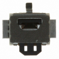
B3U-3100P-B
Description
SWITCH TACT SPST SIDE ACT W/BOSS
Manufacturer
Omron
Series
B3Ur
Specifications of B3U-3100P-B
Circuit
SPST-NO
Switch Function
Off-Mom
Contact Rating @ Voltage
0.05A @ 12VDC
Actuator Type
Rectangular Button
Mounting Type
Surface Mount
Orientation
Right Angle
Outline
3.00mm x 2.50mm
Illumination
Non-Illuminated
Operating Force
162gf
Actuator
Side
Contact Form
SPST - NO
Termination Style
Solder Pad
Features
Ultra-Small-Sized Tactile Switch with High Contact Reliability
Operating Temperature Range
- 25 C to + 70 C
Contact Configuration
SPST-NO
Contact Voltage Dc Nom
12V
Contact Current Max
50mA
Actuation Type
Side
Switch Terminals
SMD
Circuitry
SPST-NO
Operating Force Max
162gf
Rohs Compliant
Yes
Actuator / Cap Color
Black
Lead Free Status / RoHS Status
Lead free / RoHS Compliant
Lead Free Status / RoHS Status
Lead free / RoHS Compliant, Lead free / RoHS Compliant
Other names
B3U-3100P-B CHN
B3U-3100P-B
B3U3100PB
B3U3100PBCHN
SW1103TR
B3U-3100P-B
B3U3100PB
B3U3100PBCHN
SW1103TR
Available stocks
Company
Part Number
Manufacturer
Quantity
Price


Precautions
B3FS-1050P
B3S
Note:
Standards
Package
Heat resistance
Standards
Package
Heat resistance
Tape drawing direction
Switches with ground terminals are packaged with the
ground terminal on the opposite side of the guide hole.
1.5
8.7
+0.1
0
dia.
0.06
Reel
Reel (made of paper)
7
(22)
1.5
+0.1
12±
0
13 dia.
4±
dia.
Tape drawing direction
Label
0.1
Conforms to JEITA.
1,000 Switches
60 ° C for 24 hours (without deformation)
Conforms to JEITA.
1,000 Switches
50 ° C for 24 hours (without deformation)
0.1
9.4
1.5
12±
2
4±
Tape drawing direction
0.1
Tape drawing direction
0.1
1.75±
0.4
380±2 dia.
7.5
Label
0.1
2
330 dia.
16±
4.7
13 dia.
0.3
1.75
7.5
(8.1)
16
21.5
LEDs (B3J)
Make sure that the polarity of the LEDs is correct. The polarity is
not indicated on the Switch, but the positive pole is located on the
back surface of the Switch on the side without the OMRON mark.
Connect limiting resistors to the LEDs. The Switch does not have
built-in limiting resistors, so satisfy the LED characteristics by
obtaining the limiting resistance according to the following formula
based on the voltage to be used.
Limiting resistance (R)=
0.5
50
30
10
50
40
30
20
10
5
3
1
0
−20
1.5
1.6
(Voltage used (E) – LED forward voltage (VF))
R
0
1.7
E
Green
Yellow
LED forward current (IF)
20
Red
I
V
F
F
Ambient temperature Ta (°C)
1.8
40
Forward voltage V
1.9
Red
Yellow/Green
60
Precautions
2.0
F
2.1
(V)
80
(Ω)
7
Related parts for B3U-3100P-B
Image
Part Number
Description
Manufacturer
Datasheet
Request
R

Part Number:
Description:
Pad Switch,SPST,SURFACE MOUNT Terminal,PCB Hole Count:1
Manufacturer:
Omron
Datasheet:
Part Number:
Description:
SWITCH TACTILE SPST-NO .05A SMD
Manufacturer:
Omron
Datasheet:
Part Number:
Description:
SWITCH TACT SPST W/O GND SMD
Manufacturer:
Omron
Datasheet:

Part Number:
Description:
Pad Switch,SPST,SURFACE MOUNT Terminal
Manufacturer:
Omron
Datasheet:

Part Number:
Description:
Pad Switch,SPST,SURFACE MOUNT Terminal
Manufacturer:
Omron
Datasheet:

Part Number:
Description:
Pad Switch,SPST,SURFACE MOUNT Terminal
Manufacturer:
Omron
Datasheet:
Part Number:
Description:
Pad Switch,SPST,SURFACE MOUNT Terminal,PCB Hole Count:1
Manufacturer:
Omron
Datasheet:

Part Number:
Description:
Tactile & Jog Switches Top Actuate w/Boss w/out Ground Term
Manufacturer:
Omron
Datasheet:
Part Number:
Description:
Tactile & Jog Switches Top Act. w/out Boss w/out Ground Term
Manufacturer:
Omron
Part Number:
Description:
Tactile & Jog Switches Top Actuated Ground Tm w/out Boss
Manufacturer:
Omron
Datasheet:
Part Number:
Description:
Pad Switch,SPST,SURFACE MOUNT Terminal,PCB Hole Count:1
Manufacturer:
Omron
Datasheet:
Part Number:
Description:
Pad Switch,SPST,SURFACE MOUNT Terminal
Manufacturer:
Omron
Datasheet:
Part Number:
Description:
Pad Switch,SPST,SURFACE MOUNT Terminal
Manufacturer:
Omron
Datasheet:

Part Number:
Description:
G6S-2GLow Signal Relay
Manufacturer:
Omron Corporation
Datasheet:
Part Number:
Description:
Compact, Low-cost, SSR Switching 5 to 20 A
Manufacturer:
Omron Corporation
Datasheet: