D2FW-G283M Omron, D2FW-G283M Datasheet - Page 4
D2FW-G283M
Manufacturer Part Number
D2FW-G283M
Description
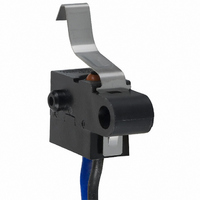
SWITCH LONGLEVER SPST-NO 1A SLD
Manufacturer
Omron
Series
D2FW-Gr
Type
Snap Actionr
Specifications of D2FW-G283M
Circuit
SPST-NO
Switch Function
Off-Mom
Contact Rating @ Voltage
1A @ 30VDC
Actuator Type
Lever, Leaf
Mounting Type
Chassis Mount
Termination Style
Wire Leads
Operating Force
300gf
Contact Form
SPST - NO
Contact Rating
1 Amp at 30 Volts
Actuator
Lever, Leaf
Microswitch Type
Subminiature
Actuator Style
Leaf Lever
Operating Force Max
300gf
Contact Voltage Dc Nom
30V
Contact Current Max
1A
Switch Terminals
Wire Leaded
Circuitry
SPST-NO
Body Style
Subminiature
Current, Rating
1 A
Dielectric Strength
1500 VAC
Ip Rating
IP67
Mounting Hole Size
4 mm
Number Of Poles
1
Operation
Snap Action
Termination
Lead Wire
Voltage, Rating
30 VDC
Mounting
Screw
Lead Free Status / RoHS Status
Lead free / RoHS Compliant
Lead Free Status / RoHS Status
Lead free / RoHS Compliant, Lead free / RoHS Compliant
Other names
D2FWG283M
SW514
SW514


Precautions
Use the Switch within the specified electrical ratings. Using the
Switch outside of the rated values will not only shorten its service life
but may cause heat generation or fire damage. When turning the
power ON or OFF, use the rated voltage and current.
■ Enclosure Ratings
Do Not Use the Switch Underwater
The Switch was tested and found to meet the conditions necessary
to meet the following standard. The test checks for water intrusion
after immersion for a specified time period. The test does not check
for switching operation underwater.
IEC Publication 529, degree of protection IP67.
Protection Against Chemicals
Prevent the Switch from coming into contact with oil or chemicals, to
avoid damaging (or deterioration of) Switch materials.
■ Mounting
Preparation for Mounting
Turn the power OFF before (1) mounting or removing the Switch, or
(2) before performing maintenance or inspection. Failure to do so can
cause electrical shock or fire.
Mount the Switch on a flat surface. If it is mounted on an uneven sur-
face the Switch may bend, causing a malfunction or cracking the
housing.
Mounting the Switch
Mount the switch securely, using an M4 screw with a flat washer or
spring washer. Tighten the screw to a torque of 1.18 to 1.47 NS m.
When mounting the switch, do not apply any external pressure to the
actuator in a direction other than the direction of operation.
The following diagram shows the mounting hole dimensions.
Mounting Holes
4
Watertight Snap Action Switch
D2FW-G
■ Operation
Make sure that the switching object is perfectly separated from the
actuator when the switch is not operated and the actuator is pressed
appropriately by the switching object when the switch is operated.
The switching object must not move beyond its operational limit posi-
tion.
Position the switching object so that its moving direction is the same
as that of the actuator.
■ Using the Switch with Micro
Even when the Switch is used within the appropriate operating
range, power surges may shorten its service life. Insert a contact pro-
tection circuit as required.
Micro application loads are indicated by N standard reference values.
This value represents the failure rate at a 60% (λ60) reliability level.
(JIS C5003)
The equation λ60 = 0.5 x 10
of 1/2,000,000 operations can be expected at a reliability level of
60%.
Model
Micro application load
Loads
D2FW-G0j
5 VDC, 1 mA
-6
/operations indicates that a failure rate
D2FW-G2j
5 VDC, 100 mA
Related parts for D2FW-G283M
Image
Part Number
Description
Manufacturer
Datasheet
Request
R

Part Number:
Description:
SWITCH BASIC SPDT .1A SLD
Manufacturer:
Omron
Datasheet:

Part Number:
Description:
SWITCH BASIC SPDT 1A SLD
Manufacturer:
Omron
Datasheet:

Part Number:
Description:
SWITCH LEVER SPST-NO .1A SEALED
Manufacturer:
Omron
Datasheet:

Part Number:
Description:
SWITCH LEVER SPST-NO 1A SEALED
Manufacturer:
Omron
Datasheet:

Part Number:
Description:
SWITCH LONGLEVER SPST-NO .1A SLD
Manufacturer:
Omron
Datasheet:

Part Number:
Description:
SWITCH BASIC SPST-NC .1A SLD
Manufacturer:
Omron
Datasheet:
Part Number:
Description:
SWITCH BASIC SPST-NC 1A SLD
Manufacturer:
Omron
Datasheet:
Part Number:
Description:
SWITCH BASIC SPST-NC 1A SLD
Manufacturer:
Omron
Datasheet:
Part Number:
Description:
SWITCH BASIC SPST-NC .1A SLD
Manufacturer:
Omron
Datasheet:
Part Number:
Description:
SWITCH BASIC SPDT .1A SLD
Manufacturer:
Omron
Datasheet:
Part Number:
Description:
SWITCH BASIC SPDT 1A SLD
Manufacturer:
Omron
Datasheet:

Part Number:
Description:
G6S-2GLow Signal Relay
Manufacturer:
Omron Corporation
Datasheet:
Part Number:
Description:
Compact, Low-cost, SSR Switching 5 to 20 A
Manufacturer:
Omron Corporation
Datasheet: