ZE-N-2G Omron, ZE-N-2G Datasheet - Page 8
ZE-N-2G
Manufacturer Part Number
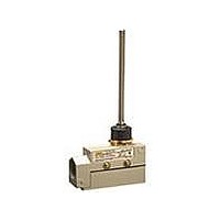
ZE-N-2G
Description
SWITCH LIMIT PLUNGER SPDT 15A
Manufacturer
Omron
Series
ZEr
Datasheet
1.ZE-NJ-2S.pdf
(10 pages)
Specifications of ZE-N-2G
Circuit
SPDT
Switch Function
On-Mom
Contact Rating @ Voltage
15A @ 125VAC
Actuator Type
Round (Pin Plunger)
Mounting Type
Chassis Mount
Termination Style
Screw Terminal
Operating Force
785gf
Contact Form
SPDT
Contact Rating
10 Amps
Actuator
Plunger, Sealed
Lead Free Status / RoHS Status
Lead free / RoHS Compliant
Lead Free Status / RoHS Status
Lead free / RoHS Compliant, Lead free / RoHS Compliant
Other names
ZEN2G


Sealed Roller Arm Lever
ZV(2)-NA2-2
XV(2)-NA2-2
Note: Unless otherwise specified, a tolerance of ±0.4 mm applies to all dimensions.
Safety Precautions
Refer to Safety Precautions for All Limit Switches.
Operating Environment
OF max.
RF min.
PT max.
OT min.
MD max.
• Seal material may deteriorate if a Switch is used outdoor or where
• Be sure to protect part A with grease in order to maintain the
subject to special cutting oils, solvents, or chemicals. Always
appraise performance under actual application conditions and set
suitable maintenance and replacement periods.
mechanical durability and performance of the Limit Switch. The use
of molybdenum disulfide grease is recommended.
3
Precautions for Correct Use
ZV-NA2-2
ZV2-NA2-2
0.4 mm
6.28 N
2.26 N
5 mm
6 mm
25.4
*1. Stainless sintered alloy roller
*2. Adjustment between 0° to 225°.
*3. Only the ZV2-NA2-2 and XV2-NA2-2 incorporate mounting holes.
±
0.3
19.1 dia.
Two, 5.4
JIS B0202
G1/2
Effective
thread: 4
threads min.
*3
×
9
+0.2
holes
23
0
*1
dia.
XV-NA2-2
XV2-NA2-2
Two, 4.3
0.72 mm
17
7.26 N
2.26 N
(23.1)
5.5 mm
6 mm
t=3 (ZV-NA2-2/XV-NA2-2 flanges)
53R
±
0.2 dia.
19.3
PT
75
86
±
0.2
36.6
39.7
10.6
±
0.3
ZV-NA277-2
ZV2-NA277-2
5.5
41.3
31
*2
0.4 mm
±
6.28 N
2.26 N
5 mm
6 mm
±
0.2
5
39.5
0.2
±
54
0.8
79
±
0.8
One-way Action Sealed Roller Arm Lever
ZV(2)-NA277-2
XV(2)-NA277-2
• Install Switches where they will not be directly subject to cutting
• Constantly subjecting a Switch to vibration or shock can result in
• The Switches have physical contacts. Using them in environments
chips, dust, or dirt. The Actuator and Switch must also be protected
from the accumulation of cutting chips or sludge.
wear, which can lead to contact interference with contacts,
operation failure, reduced durability, and other problems.
Excessive vibration or shock can lead to false contact operation or
damage. Install Switches in locations not subject to shock and
vibration and in orientations that will not produce resonance.
containing silicon gas will result in the formation of silicon oxide
(SiO
contacts, contact interference can occur. If silicon oil, silicon filling
agents, silicon cables, or other silicon products are present near the
Switch, suppress arcing with contact protective circuits (surge
killers) or remove the source of silicon gas.
XV-NA277-2
XV2-NA277-2
0.72 mm
Not Suitable
7.26 N
2.26 N
5.5 mm
6 mm
2
) due to arc energy. If silicon oxide accumulates on the
3
18.7 dia.
25.4
±
ZE/ZV/ZV2/XE/XV/XV2
0.3
×
9
Two, 5.4
*1
JIS B0202
G1/2
Effective
thread: 4
threads min.
*3
*1. Stainless steel roller
*2. Adjustment between 0° to 225°.
*3. Only the ZV2-NA277-2 and XV2-NA277-2 incorporate
Two, 4.3
mounting holes.
23
+0.2
holes
0
dia.
±
0.2 dia. holes
17
t=3 (ZV-NA277-2/XV-NA277-2 flanges)
(40)
53R
17.4R
Suitable
19.3
PT
75
86
±
0.2
36.6
39.7
10.6
±
0.3
5.5
41.3
Operates in this
direction only
31
±
*2
±
0.2
39.5
5
0.2
54
±
0.8
79
±
0.8
8
Related parts for ZE-N-2G
Image
Part Number
Description
Manufacturer
Datasheet
Request
R

Part Number:
Description:
SWITCH LIMIT PLUNGER SPDT 15A
Manufacturer:
Omron
Datasheet:

Part Number:
Description:
SWITCH LIMIT PLUNGER SPDT 15A
Manufacturer:
Omron
Datasheet:

Part Number:
Description:
SWITCH LIMIT SPRING SPDT 15A
Manufacturer:
Omron
Datasheet:

Part Number:
Description:
SWITCH LIMIT ROLL ARM SPDT 15A
Manufacturer:
Omron
Datasheet:

Part Number:
Description:
SWITCH LIMIT ROLL PLUNG SPDT 15A
Manufacturer:
Omron
Datasheet:
Part Number:
Description:
SWITCH LIMIT PLUNGER SPDT 15A
Manufacturer:
Omron
Datasheet:
Part Number:
Description:
SWITCH LIMIT PLUNGER SPDT 15A
Manufacturer:
Omron
Datasheet:
Part Number:
Description:
SWITCH LIMIT PLUNGER SPDT 15A
Manufacturer:
Omron
Datasheet:

Part Number:
Description:
SWITCH LIMIT ROLL PLNGR SPDT 15A
Manufacturer:
Omron
Datasheet:
Part Number:
Description:
LIMIT SWITCH
Manufacturer:
Omron
Datasheet:
Part Number:
Description:
SWITCH CROSS ROLL PLNGR SPDT 15A
Manufacturer:
Omron
Datasheet:
Part Number:
Description:
SWITCH ROLLER ARM LEVER SPDT 15A
Manufacturer:
Omron
Datasheet:

Part Number:
Description:
SWITCH LIMIT ROLL PLNGR SPDT 15A
Manufacturer:
Omron
Datasheet:
Part Number:
Description:
LIMIT SWITCH
Manufacturer:
Omron
Datasheet:
Part Number:
Description:
SWITCH ROLLER ARM LEVER SPDT 15A
Manufacturer:
Omron
Datasheet: