SS-01D Omron, SS-01D Datasheet
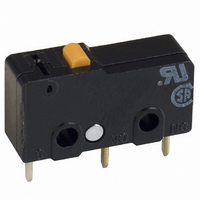
SS-01D
Specifications of SS-01D
SW155


Related parts for SS-01D


SS-01D Summary of contents
Page 1
... Rated Actuator Resistive Load - Switch SS-01 0.1A @ 125VAC/0.1A plunger @ 30VDC SS-01D 0.1A @ 125VAC/0.1A plunger @ 30VDC SS-01D1 0.1A @ 125VAC/0.1A plunger @ 30VDC 0.1A @ SS-01D2 125VAC/0.1A plunger @ 30VDC SS-01T 0.1A @ 125VAC/0.1A plunger @ 30VDC SS-01-E 0.1A @ 125VAC/0.1A plunger @ 30VDC 0.1A @ SS-01- ED 125VAC/0.1A plunger @ 30VDC 0.1A @ ...
Page 2
... Hinged roller lever Model PCB terminal Straight vertical Parallel to left Parallel to right SS-01-ED — — SS-01-FD — — SS-01D SS-01D1 SS-01D2 SS-01GL-ED — — SS-01GL-FD — — SS-01GLD SS-01GLD1 SS-01GLD2 SS-01GL13-ED — — SS-01GL13-FD — — SS-01GL13D — — — — ...
Page 3
... Humidity Service life Mechanical Electrical Weight Note: 1. SS-10 series only. 2. 50,000 operations minimum for the SS-10 series. 3. Applies to the pin plunger type (at the pin plunger of the lever type million operations for the SS-10 series. 5. Data shown are of initial value Snap Action Switch ...
Page 4
... OT min. 1.0 mm (0.039 in) MD max. 14.9 mm (0.587 in) OP 10.1 ± 0.8 mm (0.398 ± 0.032 in) ■ Ratings Microvoltage/microcurrent load type General purpose/resistive load Bifurcated crossbar contacts Contact form NC 125 VAC 0 VDC 0.1 A Inrush current 1 A max. SS-01-F SS-01 SS-5-F ...
Page 5
... SS-10 series must have a power factor of 0.75 min. 3. Lamp load has an inrush current of 10 times the steady-state current 4. Motor load has an inrush current of 6 times the steady-state current the switch is used circuit and is subjected to inrush current or surge, connect a surge suppressor across the switch. ■ Contact Resistance Contact rating: ...
Page 6
... Engineering Data ■ Mechanical service life Standard type (SS-5, SS-10 series) Dimensions Unit: mm (inch) ■ Pin Plunger SS-01 (-E, -F) SS-5 (-F) SS-10 ■ Hinge Lever SS-01GL (-E, -F) SS-5GL (-F) SS-10GL ■ Electrical service life Standard type (SS-5 series) Snap Action Switch SS 5 ...
Page 7
... SS-5GL14 (-F) SS-10GL14 Note: 1. Unless otherwise specified, a tolerance of ±0.4 mm applies to all dimensions. 2. Straight vertical PCB terminal models are shown above. Soldered terminal, Tab (#110) terminal, lead wire terminal, PCB terminal parallel to left and PCB terminal parallel to right are shown in the Terminals section. ...
Page 8
... Unit: mm (inch) ■ Terminals General-Purpose Type PCB terminal, straight vertical (D) PCB terminal, parallel to left (D1) Note: Thickness of all the terminals is 0.5 mm. Soldered terminal (blank) PCB terminal, parallel to right (D2) Quick-connect tab (#110) terminal (T) Snap Action Switch SS 7 ...