D3V-16-1C5 Omron, D3V-16-1C5 Datasheet - Page 15
D3V-16-1C5
Manufacturer Part Number
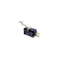
D3V-16-1C5
Description
SWITCH SNAP SPDT 16A QC TERM
Manufacturer
Omron
Series
D3Vr
Specifications of D3V-16-1C5
Operating Force
200gf
Circuit
SPDT
Switch Function
On-Mom
Contact Rating @ Voltage
16A @ 250VAC
Actuator Type
Round (Pin Plunger)
Mounting Type
Chassis Mount
Termination Style
Quick Connect - .250" (6.3mm)
Contact Form
SPDT
Contact Rating
11 Amps
Actuator
Plunger, Pin
Contact Configuration
SPDT
Microswitch Type
Snap Action
Actuation Type
Plunger
Contact Voltage Ac Nom
250V
Contact Voltage Dc Nom
250V
Contact Current Max
16A
Switch
RoHS Compliant
Actuator Style
Plunger
Operating Force Max
1.96N
Rohs Compliant
Yes
Lead Free Status / RoHS Status
Lead free / RoHS Compliant
Lead Free Status / RoHS Status
Lead free / RoHS Compliant
Other names
D3V161C5


Precautions
I Cautions
Handling
Be careful not to drop the switch. Doing so may cause damage to the
switch’s internal components because it is designed for a small load.
I Correct Use
Mounting
Use two M3 mounting screws with an appropriate screwdriver to
mount the switch. Tighten the screws to a torque of 0.39 to
0.59 N • m {4 to 6 kgf • cm}.
Mounting Direction
Mount lever-operated switches with a maximum operating force of
0.49 N in a direction where the actuator weight will not be applied to
the switch. Since the switch is designed for a small load, its resetting
force is small. Therefore, resetting failure may occur if unnecessary
load is applied to the switch.
Insulation Distance
According to EN61058-1, the minimum insulation thickness for this
switch should be 1.1 mm and minimum clearance distance between
the terminal and mounting plate should be 1.9 mm. If the insulation
distance cannot be provided in the product incorporating the switch,
either use a switch with insulation barrier or use a Separator to
ensure sufficient insulation distance.
1000
Miniature Basic Switch
D3V
Using Micro Loads
Using a model for ordinary loads to open or close the contact of a
micro load circuit may result faulty contact. Use models that operate
in the following range. However, even when using micro load models
within the operating range shown below, if inrush current occurs
when the contact is opened or closed, it may increase contact wear
and so decrease life expectancy. Therefore, insert a contact protec-
tion circuit where necessary.
The minimum applicable load is the N-level reference value. This
value indicates the malfunction reference level for the reliability level
of 60% (λ 60). The equation, λ 60 = 0.5 × 10
that the estimated malfunction rate is less than
1/2,000,000 operations with a reliability level of 60%.
Solder Terminal Approval Conditions
Use of soldering iron for normal soldering is acceptable.
Soldering hook holes version available.
Soldering terminal types 1 and 2 are met.
Inoperable
range
Operating range
for micro load
models D3V-01
Current (mA)
Operating
range for
general-
load models
−6
/operations indicates
Related parts for D3V-16-1C5
Image
Part Number
Description
Manufacturer
Datasheet
Request
R

Part Number:
Description:
MINIATURE BASIC SWITCH
Manufacturer:
Omron
Datasheet:
Part Number:
Description:
Miniature Basic Switch
Manufacturer:
Omron
Datasheet:
Part Number:
Description:
Miniature Basic Switch
Manufacturer:
Omron
Datasheet:
Part Number:
Description:
MINIATURE BASIC SWITCH
Manufacturer:
Omron
Datasheet:
Part Number:
Description:
Minature Basic Switch
Manufacturer:
Omron
Datasheet:
Part Number:
Description:
Switch, Miniature, Snap Action, SPDT, QC Terminal, 16 AMPS, INTERNAL HINGE LEVER
Manufacturer:
Omron
Datasheet:

Part Number:
Description:
SWITCH LEVER SPDT 16A .187" QC
Manufacturer:
Omron
Datasheet:
Part Number:
Description:
SWITCH LEVER SPDT 16A .187" QC
Manufacturer:
Omron
Datasheet:

Part Number:
Description:
SWITCH LEVER SPDT 16A .187" QC
Manufacturer:
Omron
Datasheet:

Part Number:
Description:
SWITCH BASIC SPDT 16A .187" QC
Manufacturer:
Omron
Datasheet:

Part Number:
Description:
SWITCH ROLL LVR SPDT 16A .187"QC
Manufacturer:
Omron
Datasheet:
Part Number:
Description:
SWITCH ROLL LVR SPDT 16A .187"QC
Manufacturer:
Omron
Datasheet:

Part Number:
Description:
SWITCH SNAP SPST-NO 16A QC TERM
Manufacturer:
Omron
Datasheet: