SSG-5L1H Omron, SSG-5L1H Datasheet - Page 2
SSG-5L1H
Manufacturer Part Number
SSG-5L1H
Description
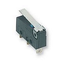
SWITCH SUBMINI SPDT 5A HINGE LVR
Manufacturer
Omron
Series
SSGr
Specifications of SSG-5L1H
Operating Force
61gf
Circuit
SPDT
Switch Function
On-Mom
Contact Rating @ Voltage
5A @ 125VAC
Actuator Type
Lever, Straight
Mounting Type
Chassis Mount
Termination Style
Solder Lug
Contact Configuration
SPDT
Microswitch Type
Snap Action
Actuation Type
Lever
Contact Voltage Ac Nom
250V
Contact Voltage Dc Nom
250V
Contact Current Max
5A
Switch Terminals
Solder
Actuator Style
Lever
Operating Force Max
0.6N
Rohs Compliant
Yes
Actuator
Lever
Contact Form
SPDT
Contact Rating
5 Amps at 125 Volts, 4 Amps at 30 Volts
Lead Free Status / RoHS Status
Lead free / RoHS Compliant
Lead Free Status / RoHS Status
Lead free / RoHS Compliant, Lead free / RoHS Compliant
Other names
SSG5L1H


Specifications
■ Characteristics
Note: 1. Data shown are of initial value.
■ Ratings
General Ratings
Note: 1. The values in the parentheses are for the SSG-01.
110
Operating speed
Operating frequency
Insulation resistance
Contact resistance
Dielectric strength (See note 2)
Vibration resistance (see note 3)
Shock resistance (see note 3)
Degree of protection
Degree of protection against
electric shock
Proof tracking index (PTI)
Ambient operating temperature
Ambient operating humidity
Service life
Weight
125 VAC
250 VAC
8 VDC
14 VDC
30 VDC
125 VDC
250 VDC
voltage
Rated
2. The dielectric strength values shown is measured using a separator between the switch and metal mounting plate.
3. For pin plunger models, the above values apply for use at the free position and total travel position. For the lever models, the values apply
2. The above current ratings are the values of the steady-state current.
3. Inductive load has a power factor of 0.7 min. (AC) and a time constant of 7 ms max. (DC).
4. Lamp load has an inrush current of 10 times the steady-state current.
5. Motor load has an inrush current of 6 times the steady-state current.
6. If the Switch is used in a DC circuit and is subjected to a surge current, connect a surge suppressor across the switch.
7. The electrical rating applies under the following test conditions:
at the total travel position with contact separation = 10μs max.
Ambient Temperature = 20±2°C, Ambient Humidity = 65±5%, Operating frequency = 30 operations/minute
Subminiature Basic Switch
NC
Resistive load
5 A (0.1 A)
4 A(0.1 A)
0.4 A
0.2 A
3 A
5 A
5 A
NO
0.1 mm to 1 m/second (pin plunger models)
Mechanical: 400 operations per minute max.
Electrical: 30 operations per minute max.
100 MΩ
153 gf:
51 gf:
1,000 VAC (600 VAC for SSG-01H and SSG-01T), 50/60 Hz for 1 minute between contacts of same polarity
1,500 VAC, 50/60 Hz for 1 minute between each terminal and ground and between each terminal and
non-current-carrying metal parts
Malfunction: 10 to 2,000 Hz, 196 m/s
Malfunction: 490 m/s
IEC IP40
Class I
175
-25° to 125°C (at 60% RH max.) with no icing
85% max. (for 5°C to 35°C)
Mechanical: 10 million operations min. at 60 operations per minute
Electrical: 200,000 operations min. at 30 operations per minute
Approx. 1.6 g pin plunger type
SSG
SSG-5 models
SSG-01 models:
SSG-5 models:
SSG-01 models
1.5 A
NC
1 A
Lamp load
0.05 A
0.03 A
2
2 A
2 A
2 A
(approx. 50G) max.
0.7 A
0.5 A
NO
:
2
(Approx. 20G)
30 mΩ max.
50 mΩ max.
100 mΩ max.
50 mΩ max.
NC
Inductive load
0.4 A
0.2 A
3 A
2 A
5 A
4 A
3 A
NO
2.5 A
1.5 A
NC
Motor load
0.05 A
0.05 A
3 A
3 A
3 A
1.3 A
0.8 A
NO
Related parts for SSG-5L1H
Image
Part Number
Description
Manufacturer
Datasheet
Request
R

Part Number:
Description:
Subminiature Basic Switch
Manufacturer:
Omron
Datasheet:
Part Number:
Description:
Subminiature Basic Switch
Manufacturer:
Omron
Datasheet:
Part Number:
Description:
Subminiature Basic Switch
Manufacturer:
Omron
Datasheet:
Part Number:
Description:
SWITCH SUBMINI SPDT 5A PIN PLNGR
Manufacturer:
Omron
Datasheet:
Part Number:
Description:
SWITCH SUBMINI SPDT 5A PIN PLNGR
Manufacturer:
Omron
Datasheet:
Part Number:
Description:
SWITCH SUBMINI SPDT 5A PIN PLNGR
Manufacturer:
Omron
Datasheet:
Part Number:
Description:
SWITCH SUBMINI SPDT 5A HINGE LVR
Manufacturer:
Omron
Datasheet:
Part Number:
Description:
SWITCH SUBMINI SPDT 5A ROLL LEVR
Manufacturer:
Omron
Datasheet:
Part Number:
Description:
SWITCH SUBMINI SPDT 5A ROLL LEVR
Manufacturer:
Omron
Datasheet:
Part Number:
Description:
Subminiature Basic Switch
Manufacturer:
Omron
Datasheet:
Part Number:
Description:
Subminiature Basic Switch
Manufacturer:
Omron
Datasheet:
Part Number:
Description:
SUBMINIATURE BASIC SWITCH
Manufacturer:
Omron
Datasheet:
Part Number:
Description:
Subminiature Basic Switch
Manufacturer:
Omron
Datasheet:

Part Number:
Description:
Basic / Snap Action / Limit Switches Hinge Quick Cn #110 .6N OF 5A
Manufacturer:
Omron
Datasheet:

Part Number:
Description:
Subminiature Basic Switch
Manufacturer:
Omron
Datasheet: