SSG-5H Omron, SSG-5H Datasheet - Page 8
SSG-5H
Manufacturer Part Number
SSG-5H
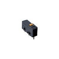
Description
SWITCH SUBMINI SPDT 5A PIN PLNGR
Manufacturer
Omron
Series
SSGr
Specifications of SSG-5H
Operating Force
153gf
Circuit
SPDT
Switch Function
On-Mom
Contact Rating @ Voltage
5A @ 125VAC
Actuator Type
Round (Pin Plunger)
Mounting Type
Chassis Mount
Termination Style
Solder Lug
Contact Form
SPDT
Contact Rating
5 Amps at 125 Volts, 4 Amps at 30 Volts
Actuator
Plunger, Pin
Contact Configuration
SPDT
Microswitch Type
Snap Action
Actuation Type
Plunger
Contact Voltage Ac Nom
250V
Contact Voltage Dc Nom
250V
Contact Current Max
5A
Switch
RoHS Compliant
Actuator Style
Plunger
Operating Force Max
1.5N
Rohs Compliant
Yes
Lead Free Status / RoHS Status
Lead free / RoHS Compliant
Lead Free Status / RoHS Status
Lead free / RoHS Compliant
Other names
SSG5H


SSG
Precautions
Mounting
Use two 2.2 mounting screws with spring washers to mount the
switch. Tighten the screws to a torque of 0.20 to 0.25 N m (2 to
2.5 kgf cm).
The switch does not have a ground terminal. The minimum distance
through insulation (IEC1058-1) is 0.9 mm. If proper insulation for the
end product cannot be secured, additional insulation such as a sep-
arator or insulation cover should be attached.
Soldering
When soldering switch terminals, apply a soldering iron rated at
60 W max. and finish soldering quickly within 3 seconds. During sol-
dering and 1 minute after soldering, do not apply external force to
the terminals.
Solder terminal is provided with a hole so that a conductor can be
secured mechanically.
The conductors for a soldering terminal (H type) should be flexible
and its cross section should be AWG18 to 20 for the SSG-5H Series
and AWG20 to 22 for the SSG-01H Series.
To automatically solder the switch to a PCB in a soldering bath, com-
plete soldering within 5 seconds at a flux temperature of 250 C and
avoid the overflow of flux onto the surface of the PCB where the
switch or other parts are mounted.
102
Cat. No. B096-E1-1
ALL DIMENSIONS SHOWN ARE IN MILLIMETERS.
To convert millimeters into inches, multiply by 0.03937. To convert grams into ounces, multiply by 0.03527.
Mounting Holes
9.5 0.1
Actuating
Make sure that the operating speed and frequency are within the
permissible range of the switch.
The reliability of a switch is maintained within the permissible oper-
ating speed and frequency of the switch. The life of a switch is deter-
mined at a specified operating speed, therefore, it varies with the ac-
tual operating speed and frequency.
The switch should be set so that its stroke will be in the range of 60%
to 90% of the rated OT when the switch is operated. The stroke must
not exceed the rated OT value.
Malfunctioning can result if the switch is set with its stroke exceed-
ing the rated OT. Therefore the proper adjustment of the mounting
position is essential when installing the switch.
Do not apply excessive force to the actuator. Be very careful not to
apply force in the opposite and lateral directions relative to the oper-
ating direction.
1. Do not use the switch in an application where the operating
2. Do not use the switch in an application where the operating
speed is extremely slow or the switching operation could
become unstable or malfunctioning could result due to
contact failure or contact welding.
speed is too fast, or the switch will be broken due to a shock or
the movable contact will not keep up with the speed.
SSG
Related parts for SSG-5H
Image
Part Number
Description
Manufacturer
Datasheet
Request
R

Part Number:
Description:
Subminiature Basic Switch
Manufacturer:
Omron
Datasheet:
Part Number:
Description:
Subminiature Basic Switch
Manufacturer:
Omron
Datasheet:
Part Number:
Description:
Subminiature Basic Switch
Manufacturer:
Omron
Datasheet:

Part Number:
Description:
SWITCH SUBMINI SPDT 5A HINGE LVR
Manufacturer:
Omron
Datasheet:
Part Number:
Description:
SWITCH SUBMINI SPDT 5A PIN PLNGR
Manufacturer:
Omron
Datasheet:
Part Number:
Description:
SWITCH SUBMINI SPDT 5A PIN PLNGR
Manufacturer:
Omron
Datasheet:
Part Number:
Description:
SWITCH SUBMINI SPDT 5A HINGE LVR
Manufacturer:
Omron
Datasheet:
Part Number:
Description:
SWITCH SUBMINI SPDT 5A ROLL LEVR
Manufacturer:
Omron
Datasheet:
Part Number:
Description:
SWITCH SUBMINI SPDT 5A ROLL LEVR
Manufacturer:
Omron
Datasheet:
Part Number:
Description:
Subminiature Basic Switch
Manufacturer:
Omron
Datasheet:
Part Number:
Description:
Subminiature Basic Switch
Manufacturer:
Omron
Datasheet:
Part Number:
Description:
SUBMINIATURE BASIC SWITCH
Manufacturer:
Omron
Datasheet:
Part Number:
Description:
Subminiature Basic Switch
Manufacturer:
Omron
Datasheet:

Part Number:
Description:
Basic / Snap Action / Limit Switches Hinge Quick Cn #110 .6N OF 5A
Manufacturer:
Omron
Datasheet:

Part Number:
Description:
Subminiature Basic Switch
Manufacturer:
Omron
Datasheet: