SS-5GL13-F Omron, SS-5GL13-F Datasheet - Page 5
SS-5GL13-F
Manufacturer Part Number
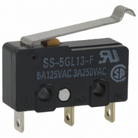
SS-5GL13-F
Description
SWITCH SIM ROLLER SPDT 5A
Manufacturer
Omron
Series
SSr
Type
Basicr
Specifications of SS-5GL13-F
Circuit
SPDT
Switch Function
On-Mom
Contact Rating @ Voltage
5A @ 125VAC
Actuator Type
Lever, Simulated Roller
Mounting Type
Chassis Mount
Termination Style
Solder Lug
Operating Force
16gf
Microswitch Type
Subminiature
Actuator Style
Simulated Roller Lever
Operating Force Max
16gf
Contact Voltage Ac Nom
250V
Contact Current Max
5A
Switch Terminals
Solder Lug
Body Style
Subminiature
Contact Form
SPDT
Current, Rating
5/4 AAC/ADC
Dielectric Strength
1500 VAC
Force, Operating
0.16 N (Max.)
Material, Casing
Stainless Steel
Mounting Hole Size
2.4 mm
Number Of Poles
1
Operation
Snap Action
Standards
UL Recognized, CSA Certified, TUV and VDE Approved
Temperature Rating
-25 to +85 °C
Termination
Solder
Voltage, Rating
125/30 VAC/VDC
Actuator
Simulated Roller Lever
Current Rating (max)
5 Amps
Voltage Rating Ac
250 Volts
Contact Rating
5 Amps at 125 Volts, 4 Amps at 30 Volts
Lead Free Status / RoHS Status
Lead free / RoHS Compliant
Lead Free Status / RoHS Status
Lead free / RoHS Compliant, Lead free / RoHS Compliant
Other names
SS-5GL13-F
SS-5GL13F
SS5GL13F
SW1006
SS-5GL13F
SS5GL13F
SW1006
Available stocks
Company
Part Number
Manufacturer
Quantity
Price
Company:

Part Number:
SS-5GL13-F
Manufacturer:
OMRON/ŷķ
Quantity:
4 088


Dimensions
■ Terminals
Note: 1. Unless otherwise specified, all units are in millimeters and a tolerance of ±0.4 mm applies to all dimensions
■ Dimensions and Operating Characteristics
Note: 1. Unless otherwise specified, all units are in millimeters and a tolerance of ±0.4 mm applies to all dimensions
Pin Plunger Models
SS-01(-E, -F)
SS-5(-F)
SS-10
Characteristics
OF max.
RF min.
PT max.
OT min.
MD max.
OP
COM
terminal
COM
terminal
(C)
Solder Terminals
PCB, Left-angled terminal
2. Terminal plate thickness is 0.5 mm for all models.
1.6
2. The following illustrations and dimensions are for solder terminal models.
3. The operating characteristics are for operation in the A direction( )
2.9
Refer to “Terminals” for models with quick-connect terminals (#110) or PCB terminals.
9.5±0.1
8.8
19.8
NO terminal
NO terminal
7.3
NC terminal
SS-01-E
3.2
NC
terminal
0.5 mm
0.5 mm
0.1 mm
25 g
2 g
6.4
6.4
OP
2.9
PT
Three,
1.6-dia. holes
6.4
2.5±0.07 dia.
2.5
2.35
COM terminal (C)
1.6
+0.075
–0.05
Note: Terminal plate thickness is 0.5 mm for all models.
COM
terminal
SS-01-F, SS-5-F
Quick-connect Terminals (#110)
5.1
2
PCB, Right-angled terminal
0.5 mm
0.1 mm
0.5 m
1.6
9.5±0.1
8.8
50 g
2.9
19.8
4 g
7.5
A
7.3
Part number
8.4 ± 0.5 mm
8.8
9.5±0.1
19.8
2.35
NO terminal
9.5
NO terminal
+0.075
–0.05
7.3
10.2
dia. holes
NC terminal
SS-01, SS-5
NC terminal
0.5 mm
0.5 mm
0.1 mm
150 g
25 g
3.2
3.2
6.4
3.2
Three, 1.2 dia.
7.1
2.8
10.6
Three, 1.6 dia.
6.4
Snap Action Switch
COM
terminal
(C)
Left-angled terminal
1.6
PCB Terminals
2.9
0.12 mm
Note: Angled terminal directions
0.6 mm
0.4 mm
SS-10
150 g
25 g
8.8
9.5±0.1
are shown below.
19.8
NO terminal
7.3
Right-angled terminal
3.3
0.5
SS
NC terminal
3.2
0.6
t = 0.5
1.2
99
7.0
Related parts for SS-5GL13-F
Image
Part Number
Description
Manufacturer
Datasheet
Request
R

Part Number:
Description:
SWITCH BASIC SPDT 5A
Manufacturer:
Omron
Datasheet:

Part Number:
Description:
SWITCH LEVER SPDT 5A
Manufacturer:
Omron
Datasheet:

Part Number:
Description:
SUBMINIATURE BASIC SWITCH
Manufacturer:
Omron
Datasheet:

Part Number:
Description:
SUBMINIATURE BASIC SWITCH
Manufacturer:
Omron
Datasheet:

Part Number:
Description:
SUBMINIATURE BASIC SWITCH
Manufacturer:
Omron
Datasheet:
Part Number:
Description:
SUBMINIATURE BASIC SWITCH
Manufacturer:
Omron
Datasheet:

Part Number:
Description:
FUSE 2.5A T-LAG IEC AMMO
Manufacturer:
Cooper/Bussmann
Datasheet:
Part Number:
Description:
FUSE 1A T-LAG IEC AMMO
Manufacturer:
Cooper/Bussmann
Datasheet:
Part Number:
Description:
FUSE 4A T-LAG IEC AMMO
Manufacturer:
Cooper/Bussmann
Datasheet:

Part Number:
Description:
SWITCH SPDT 5A PIN PLUNGER SLD
Manufacturer:
Omron
Datasheet: