D3V-11G6-1C25-K Omron, D3V-11G6-1C25-K Datasheet - Page 8
D3V-11G6-1C25-K
Manufacturer Part Number
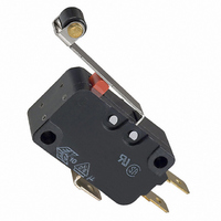
D3V-11G6-1C25-K
Description
SWITCH ROLL LVR SPDT 11A .187"QC
Manufacturer
Omron
Series
D3Vr
Type
Basicr
Specifications of D3V-11G6-1C25-K
Circuit
SPDT
Switch Function
On-Mom
Contact Rating @ Voltage
11A @ 250VAC
Actuator Type
Lever, Roller
Mounting Type
Chassis Mount
Termination Style
Quick Connect - .187" (4.7mm)
Operating Force
200gf
Microswitch Type
Miniature
Actuator Style
Hinge Roller Lever
Operating Force Max
200gf
Contact Voltage Ac Nom
250V
Contact Voltage Dc Nom
250V
Contact Current Max
11A
Body Style
Miniature
Contact Form
SPDT
Current, Rating
11 A
Dielectric Strength
2000 VAC
Force, Operating
1.96 N
Ip Rating
IP00
Mounting Hole Size
2.9 mm
Number Of Poles
1
Operation
Snap Action
Standards
UL Recognized File No. E41515, CSA Certified File No. LR21642
Temperature Rating
-25 to +105 °C
Termination
Quick Connect
Voltage, Rating
250 VAC
Lead Free Status / RoHS Status
Lead free / RoHS Compliant
Lead Free Status / RoHS Status
Lead free / RoHS Compliant, Lead free / RoHS Compliant
Other names
D3V11G61C25K
SW712
SW712


Dimensions
■ Terminals
Note: Unless otherwise specified, all units are in millimeters and a tolerance of ±0.4 mm applies to all dimensions
Note: The table above is for the SPDT contact specifications. Two terminals will be available for SPST-NO or SPST-NC contact specifications. For
■ Mounting Holes
All switches may be panel mounted using M3 mounting screws with
plane washers or spring washers to securely mount the switch.
Tighten the screws to a torque of 0.39 to 0.59 N·m.
■ Dimensions and Operating Characteristics
Note: 1. Unless otherwise specified, all units are in millimeters and a tolerance of ±0.4 mm applies to all dimensions
Plunger Models
80
D3V-21G-1@4A-Δ
D3V-16-1@5-Δ
D3V-11-1@5-Δ
D3V-11-1@4-Δ
D3V-6-1@4-Δ
D3V-6G-1@3-Δ
D3V-01-1@2-Δ
D3V-01-1@3-Δ
COM
Terminal
dimensions
OF max.
RF min.
PT max.
OT min.
MD max.
OP
Terminal
type
Model
terminal positions, refer to the above Contact Form.
2. The following illustrations and drawings are for quick-connect terminals (#187) (terminals C2). D3V models also incorporate terminals A, C, and
3. The @ in the model number is for the terminal code.
4. The Δ in the model number is for combinations of the enclosure material, the mounting hole size and the special code as indicated in the Model
5. The operating characteristics are for operation in the A direction (
C6, which are omitted from the following drawings. Refer to Terminals section for the dimensions of these terminals.
Number Legend and Available Combinations tables. The hole size in the following illustrations of models with a suffix “K” in the Δ is 2.9 mm.
Miniature Basic Switch
Note: Indicates the length to the
D3V-21G-1@4A-Δ
t = 0.5
Three, solder terminals
Solder Terminal
1.2 mm
1.0 mm
0.3 mm
center of the 1.6-dia. holes
125 gf
2.4 dia.
20 gf
(10)
(A)
1.6 dia.
3.2 (see note)
4.75±0.1
6.35
(5.5)
(6.5)
2.9
D3V-16-1@5-Δ
D3V-11-1@5-Δ
200 gf
D3V
50 gf
0.4 mm (F gap type) or 0.3 mm (G gap type)
Quick-connect Terminal
t = 0.5
Three, quick-connect
terminals (#187)
t=0.5
Three, quick-connect
terminals (#187)
(#187) (C2)
(10)
1.6-dia. terminal hole
D3V-11-1@4-Δ
D3V-6-1@4-Δ
3.2
4.75±0.1
1.2 mm
1.0 mm
100 gf
6.35
15 gf
(6.5)
(5.5)
2.9
14.7±0.4 mm
).
Quick-connect Terminal
D3V-6G-1@3-Δ
t = 0.8 Three, quick-connect
3.95
50 gf
5 gf
terminals (#250)
(#250) (C)
1.65-dia. terminal hole
A
(12.0)
8
(4.9)
(7.7)
3.2
6.35±0.1
Two, 3.1-dia. mounting holes or
M3 screw holes
22.2±0.1
D3V-01-1@3-Δ
50 gf
5 gf
10.3±0.1
Quick-connect RAST5
Terminals (#250)(C6)
12.8
1.2 mm
1.0 mm
0.4 mm
1.75-dia. terminal hole
16.8
(3.5)
D3V-01-1@2-Δ
t=0.8
Three quick connect
terminals (#250)
5
25 gf
4.5
3 gf
15.2
6.3±0.1
Related parts for D3V-11G6-1C25-K
Image
Part Number
Description
Manufacturer
Datasheet
Request
R

Part Number:
Description:
SWITCH ROLLER SPDT 11A QC TERM
Manufacturer:
Omron
Datasheet:

Part Number:
Description:
Miniature Basic Switch
Manufacturer:
Omron
Datasheet:

Part Number:
Description:
MINIATURE BASIC SWITCH
Manufacturer:
Omron
Datasheet:
Part Number:
Description:
MINIATURE BASIC SWITCH
Manufacturer:
Omron
Datasheet:
Part Number:
Description:
Miniature Basic Switch
Manufacturer:
Omron
Datasheet:
Part Number:
Description:
Miniature Basic Switch
Manufacturer:
Omron
Datasheet:
Part Number:
Description:
Miniature Basic Switch
Manufacturer:
Omron
Datasheet:
Part Number:
Description:
Snap Action Switch
Manufacturer:
Omron
Datasheet:

Part Number:
Description:
SWITCH LEVER SPDT 11A QC TERM
Manufacturer:
Omron
Datasheet:

Part Number:
Description:
SWITCH LEVER SPDT 11A .187" QC
Manufacturer:
Omron
Datasheet:

Part Number:
Description:
SWITCH LEVER SPDT 11A .187" QC
Manufacturer:
Omron
Datasheet:

Part Number:
Description:
SWITCH LEVER SPDT 11A .187" QC
Manufacturer:
Omron
Datasheet:
Part Number:
Description:
Basic / Snap Action / Limit Switches LEVER 11A
Manufacturer:
Omron
Datasheet:
Part Number:
Description:
MINIATURE BASIC SWITCH
Manufacturer:
Omron
Datasheet:
Part Number:
Description:
MINIATURE BASIC SWITCH
Manufacturer:
Omron
Datasheet: