SS-5-F Omron, SS-5-F Datasheet - Page 3
SS-5-F
Manufacturer Part Number
SS-5-F
Description
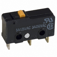
SWITCH SPDT 5A PIN PLUNGER SLD
Manufacturer
Omron
Series
SSr
Type
Basic Switchesr
Specifications of SS-5-F
Circuit
SPDT
Switch Function
On-Mom
Contact Rating @ Voltage
5A @ 125VAC
Actuator Type
Round (Pin Plunger)
Mounting Type
Chassis Mount
Termination Style
Solder Lug
Operating Force
50gf
Microswitch Type
Subminiature
Actuator Style
Pin Plunger
Operating Force Max
50gf
Contact Voltage Ac Nom
250V
Contact Current Max
5A
Switch Terminals
Solder Lug
Circuitry
SPDT
Actuator
Plunger, Pin
Contact Form
SPDT
Current Rating (max)
5 Amps
Voltage Rating Ac
250 Volts
Contact Rating
5 Amps at 125 Volts, 4 Amps at 30 Volts
Post Position
Straight Vertical
Lead Free Status / RoHS Status
Lead free / RoHS Compliant
Lead Free Status / RoHS Status
Lead free / RoHS Compliant, Lead free / RoHS Compliant
Other names
SS-5-F
SS5F
SW870
SS5F
SW870
Available stocks
Company
Part Number
Manufacturer
Quantity
Price

Part Number:
SS-5-F
Manufacturer:
OMRON/欧姆龙
Quantity:
20 000


■ Ratings
Note: 1. Data in parentheses apply to the SS-10 models only.
■ Approved Standards
UL Recognized (File No. E41515)
CSA Certified (File No. LR21642)
EN61058-1 - - VDE approval
(File No. 129246 for SS-5, 125256 for SS-10)
EN61058-1 - - TÜV Rheinland approval
(File No. J9451450)
Testing conditions: 5E4 (50,000 operations), T85 (0°C to 85°C)
Note: The rated values approved by each of the safety standards
Contact form
125 VAC
250 VAC
8 VDC
14 VDC
30 VDC
125 VDC
250 VDC
Rated Voltage
125 VAC
250 VAC
30 VDC
Rated Voltage
250 VAC
Rated Voltage
250 VAC
Switch series:
2. The above current ratings are the values of the steady-state current.
3. Inductive load has a power factor of 0.4 min. (AC) and a time constant of 7 ms max. (DC). The inductive load rating of the SS-10 is the
4. Lamp load has an inrush current of 10 times the steady-state current
5. Motor load has an inrush current of 6 times the steady-state current.
6. If the switch is used in a DC circuit and is subjected to inrush current or surge, connect a surge suppressor across the switch.
7. The electrical rating applies under the following test conditions:
(e.g. UL, CSA) may be different from the performance charac-
teristics individually defined in this catalog.
same as that of SS-5.
Ambient Temperature = 20±2°C, Ambient Humidity = 65±5%, Operating frequency = 30 operations/minute
(reference values)
10.1 A
SS-10
- - -
- - -
NC
Resistive load
5 A (10.1A)
3 A (10.1A)
5 A (10.1A)
5 A (10.1A)
10.1 A
10.1 A
SS-10
SS-10
0.4 A
0.2 A
4 A
NO
SS-5
- - -
5 A
3 A
SS-5
SS-5
1.5 A
5 A
5 A
NC
1 A
Lamp load
0.05 A
0.03 A
2 A
2 A
2 A
SS-01
0.1 A
0.1 A
- - -
0.7 A
0.5 A
SS-10 and SS-5
NO
NC
5 A
Inductive load
■ Contact Specifications
Note: Minimum applicable loads are indicated by N standard refer-
Specification
Material
Gap (standard value)
Inrush current
Minimum applicable
load (see note)
0.4 A
0.2 A
3 A
2 A
4 A
3 A
ence values. This value represents the failure rate at a 60%
(λ
The equation
rate of 1/2,000,000 operations can be expected at a reliability
level of 60%
60
Item
) reliability level (JIS C5003).
NO
4 A
λ
60
Snap Action Switch
2.5 A
1.5 A
NC
=0.5 x 10
NC: 20A max.
NO: 15A max.
Motor load
Silver alloy
0.05 A
0.03 A
SS-10
3 A
3 A
3 A
160 mA at 5 VDC
-6
1.3 A
0.8 A
/ operations indicates that a failure
0.5 mm
NO
Rivet
NC: 20A max.
NO: 10A max.
Silver
SS-5
Resistive Load
NC
SS
SS-01
0.1 A
0.1 A
0.1 A
0.1 A
- - -
- - -
- - -
1 mA at 5 VDC
Gold alloy
Crossbar
0.25 mm
1A max.
SS-01
NO
97
Related parts for SS-5-F
Image
Part Number
Description
Manufacturer
Datasheet
Request
R

Part Number:
Description:
SWITCH SPDT 5A PIN PLUNGER SLD
Manufacturer:
Omron
Datasheet:

Part Number:
Description:
PIN PLUNGER SPDT 1.8OZ/5AMP
Manufacturer:
Omron
Datasheet:

Part Number:
Description:
SUBMINIATURE BASIC SWITCH
Manufacturer:
Omron
Datasheet:
Part Number:
Description:
SUBMINIATURE BASIC SWITCH
Manufacturer:
Omron
Datasheet:

Part Number:
Description:
MICRO SWITCH, PIN PLUNGER, SPDT, 5A 250V
Manufacturer:
Omron
Datasheet: