SS-5-F Omron, SS-5-F Datasheet - Page 9
SS-5-F
Manufacturer Part Number
SS-5-F
Description
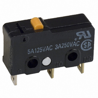
SWITCH SPDT 5A PIN PLUNGER SLD
Manufacturer
Omron
Series
SSr
Type
Basic Switchesr
Specifications of SS-5-F
Circuit
SPDT
Switch Function
On-Mom
Contact Rating @ Voltage
5A @ 125VAC
Actuator Type
Round (Pin Plunger)
Mounting Type
Chassis Mount
Termination Style
Solder Lug
Operating Force
50gf
Microswitch Type
Subminiature
Actuator Style
Pin Plunger
Operating Force Max
50gf
Contact Voltage Ac Nom
250V
Contact Current Max
5A
Switch Terminals
Solder Lug
Circuitry
SPDT
Actuator
Plunger, Pin
Contact Form
SPDT
Current Rating (max)
5 Amps
Voltage Rating Ac
250 Volts
Contact Rating
5 Amps at 125 Volts, 4 Amps at 30 Volts
Post Position
Straight Vertical
Lead Free Status / RoHS Status
Lead free / RoHS Compliant
Lead Free Status / RoHS Status
Lead free / RoHS Compliant, Lead free / RoHS Compliant
Other names
SS-5-F
SS5F
SW870
SS5F
SW870
Available stocks
Company
Part Number
Manufacturer
Quantity
Price

Part Number:
SS-5-F
Manufacturer:
OMRON/欧姆龙
Quantity:
20 000


SS
Precautions
Refer to General Information.
■
Terminal Connection
When soldering the lead wire to the terminal, first insert the lead
wire conductor through the terminal hole and then conduct sol-
dering.
Make sure that the capacity of the soldering iron is 60 W maxi-
mum. Do not take more than 350°C for the temperature at the tip
of the soldering iron. Do not take more than 5 s to solder the
switch terminal. Improper soldering involving an excessively high
temperature or excessive soldering time may deteriorate the char-
acteristics of the Switch.
Be sure to apply only the minimum required amount of flux. The
Switch may have contact failures if flux intrudes into the interior of
the Switch.
Use the following lead wires to connect to the solder terminals.
If the PCB terminal models are soldered in the solder bath, flux
will permeate inside the Switch and cause contact failure. There-
fore, manually solder the PCB terminal.
Wire the quick-connect terminals (#110) with receptacles. Insert
the terminals straight into the receptacles. Do not impose exces-
sive force on the terminal in the horizontal direction, otherwise the
terminal may be deformed or the housing may be damaged.
Insulation Distance
According to EN61058-1, the minimum insulation thickness for
this Switch should be 1.1 mm and minimum clearance distance
between the terminal and mounting plate should be 1.6 mm. If the
insulation distance cannot be provided in the product incorporat-
ing the Switch, either use a Switch with insulation barrier or use a
Separator to ensure sufficient insulation distance. Refer to Sepa-
rator.
■
Mounting
Turn OFF the power supply before mounting or removing the
Switch, wiring, or performing maintenance or inspection. Failure
to do so may result in electric shock or burning.
Use M2.3 mounting screws with plane washers or spring washers
to securely mount the Switch. Tighten the screws to a torque of
0.23 to 0.26 N·m {2.3 to 2.7 kgf·cm}.
Mount the Switch onto a flat surface. Mounting on an uneven sur-
face may cause deformation of the Switch, resulting in faulty oper-
ation or breakage in the housing.
Operating Stroke Setting
Take particular care in setting the operating stroke for the pin
plunger models. Make sure that the operating stroke is 70% to
100% of the rated OT distance. Do not operate the actuator
exceeding the OT distance, otherwise the durability of the Switch
may be shortened.
Cat. No. B032-E1-12
SS-5
SS-10
Cautions
Correct Use
Model
ALL DIMENSIONS SHOWN ARE IN MILLIMETERS.
To convert millimeters into inches, multiply by 0.03937. To convert grams into ounces, multiply by 0.03527.
0.5 to 0.75 mm
0.75 mm
2
Conductor size
2
Using Micro Loads
Using a model for ordinary loads to open or close the contact of a
micro load circuit may result in faulty contact. Use models that
operate in the following range. However, even when using micro
load models within the operating range shown below, if inrush
current occurs when the contact is opened or closed, it may
increase contact wear and so decrease durability. Therefore,
insert a contact protection circuit where necessary.
The minimum applicable load is the N-level reference value. This
value indicates the malfunction reference level for the reliability
level of 60% (λ 60). The equation, λ 60 = 0.5×10
indicates that the estimated malfunction rate is less than 1/
2,000,000 operations with a reliability level of 60%.
■
Note:
■
Refer to Terminal Connectors.
Separator for SS@
SS, D2S, D2SW
Separators
Connector
Applicable
Switch
The material is EAVTC (Epoxide Alkyd Varnished Tetron
Cloth) and its heat-resisting temperature is 130°C.
Inoperable
range
0.18
0.4
Thickness (mm)
Operating range
for micro load
models SS-01
Separator
Separator for SS0.18
Separator for SS0.4
Current (mA)
Model (see note)
Operating
range for
general-load
models
SS-5, SS-10
–6
/operations
SS
9
Related parts for SS-5-F
Image
Part Number
Description
Manufacturer
Datasheet
Request
R

Part Number:
Description:
SWITCH SPDT 5A PIN PLUNGER SLD
Manufacturer:
Omron
Datasheet:

Part Number:
Description:
PIN PLUNGER SPDT 1.8OZ/5AMP
Manufacturer:
Omron
Datasheet:

Part Number:
Description:
SUBMINIATURE BASIC SWITCH
Manufacturer:
Omron
Datasheet:
Part Number:
Description:
SUBMINIATURE BASIC SWITCH
Manufacturer:
Omron
Datasheet:

Part Number:
Description:
MICRO SWITCH, PIN PLUNGER, SPDT, 5A 250V
Manufacturer:
Omron
Datasheet: