J-7 Omron, J-7 Datasheet - Page 2
J-7
Manufacturer Part Number
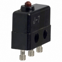
J-7
Description
SWITCH BASIC SPDT 7A TURRET
Manufacturer
Omron
Series
Jr
Type
Snap Actionr
Specifications of J-7
Circuit
SPDT
Switch Function
On-Mom
Contact Rating @ Voltage
7A @ 250VAC
Actuator Type
Round (Pin Plunger)
Mounting Type
Chassis Mount
Termination Style
Solder Turret
Operating Force
140gf
Contact Form
SPDT
Contact Rating
7 Amps at 250 Volts
Actuator
Plunger, Pin
Microswitch Type
Ultra Subminiature
Actuator Style
Pin Plunger
Operating Force Max
140gf
Contact Voltage Ac Nom
250V
Contact Voltage Dc Nom
250V
Contact Current Max
7A
Body Style
Ultra Subminiature
Current, Rating
7 A
Dielectric Strength
1500 VAC
Ip Rating
IP40
Mounting Hole Size
M2.3
Number Of Poles
1
Operation
Snap Action
Termination
Screw
Voltage, Rating
125/250 VAC
Lead Free Status / RoHS Status
Lead free / RoHS Compliant
Lead Free Status / RoHS Status
Lead free / RoHS Compliant, Lead free / RoHS Compliant
Other names
J7
SW813
Z2166
Z2166
SW813
Z2166
Z2166


J
Specifications
Note: The ratings values apply under the following test conditions:
Note: 1. The above values are for the steady-state current.
Note: 1. The data given above are initial values.
204
125 VAC
250 VAC
125 VAC
250 VAC
8 VDC
14 VDC
30 VDC
125 VDC
250 VDC
Operating speed
Operating frequency
Insulation resistance
Contact resistance (initial value)
Dielectric strength
Vibration resistance (see note 2)
Shock resistance (see note 2, 3)
Durability (see note 4)
Degree of protection
Degree of protection against
electric shock
Proof tracking index (PTI)
Ambient operating temperature
Ambient operating humidity
Weight
Ratings
Switching Capacity per Load (Reference Values)
Characteristics
Voltage
Rated voltage
Ambient temperature: 20±2°C
Ambient humidity: 65±5%
Operating frequency: 30 operations/min
2. Inductive load has a power factor of 0.4 min. (AC) and a time constant of 7 ms max. (DC).
3. Lamp load has an inrush current of 10 times the steady-state current.
4. Motor load has an inrush current of 6 times the steady-state current.
2. Malfunction: 1 ms max.
3. For the pin plunger models, the values are at the free position and total travel position. For the lever models, they are at the total
4. For testing conditions, consult your OMRON sales representative.
travel position.
NC
Resistive load
7 A
7 A
0.4 A
0.2 A
7 A
7 A
7 A
7 A
5 A
Resistive load
Non-inductive load
0.05 mm to 1 m/s (pin plunger models)
Mechanical: 400 operations/min max.
Electrical:
100 MΩ min. (at 500 VDC)
15 mΩ max.
600 VAC, 50/60 Hz for 1 min between terminals of the same polarity
1,500 VAC, 50/60 Hz for 1 min between each terminal and non-current-carrying metal part and
between current-carrying metal part and ground.
Malfunction: 10 to 55 Hz, 1.5-mm double amplitude
Destruction: 1,000 m/s
Malfunction: 200 m/s
Mechanical: 10,000,000 operations min. (60 operations/min)
Electrical:
IEC IP40
Class I
175
–10°C to 80°C (at ambient humidity of 60% max.) (with no icing)
85% max. (for 5°C to 35°C)
Approx. 1 g (pin plunger models)
NO
30 operations/min max.
50,000 operations min. (30 operations/min)
1.5 A
1.5 A
1.5 A
1.5 A
1.5 A
0.4 A
0.2 A
NC
Lamp load
2
{approx. 20G} max. (pin plunger models)
2
{approx. 100G} max.
0.7 A
0.7 A
0.7 A
0.7 A
0.7 A
0.4 A
0.2 A
NO
NC
Inductive load
0.03 A
0.02 A
4 A
4 A
3 A
3 A
3 A
NO
Inductive load
0.03 A
0.02 A
2.5 A
2.5 A
2.5 A
2.5 A
2.5 A
NC
Motor load
0.03 A
0.02 A
1.3 A
1.3 A
1.3 A
1.3 A
1.3 A
NO
J
Related parts for J-7
Image
Part Number
Description
Manufacturer
Datasheet
Request
R

Part Number:
Description:
SWITCH ROLLER LVR SPDT 7A TURRET
Manufacturer:
Omron
Datasheet:

Part Number:
Description:
SWITCH HINGE LVR SPDT 7A TURRET
Manufacturer:
Omron
Datasheet:

Part Number:
Description:
MICRO SWITCH, ROLLER LEVER, SPDT 7A 250V
Manufacturer:
Omron
Datasheet:

Part Number:
Description:
SWITCH SHORT LVR SPDT 7A TURRET
Manufacturer:
Omron
Datasheet:

Part Number:
Description:
SWITCH LONG LEVER SPDT 7A TURRET
Manufacturer:
Omron
Datasheet:

Part Number:
Description:
SUBMINIATURE BASIC SWITCH
Manufacturer:
Omron
Datasheet:
Part Number:
Description:
SUBMINIATURE BASIC SWITCH
Manufacturer:
Omron
Datasheet:

Part Number:
Description:
Temperature Controller
Manufacturer:
Omron
Datasheet:
Part Number:
Description:
Temperature Controller
Manufacturer:
Omron
Datasheet:
Part Number:
Description:
Temperature Controller
Manufacturer:
Omron
Datasheet:
Part Number:
Description:
Temperature Controller
Manufacturer:
Omron
Datasheet:

Part Number:
Description:
G6S-2GLow Signal Relay
Manufacturer:
Omron Corporation
Datasheet:
Part Number:
Description:
Compact, Low-cost, SSR Switching 5 to 20 A
Manufacturer:
Omron Corporation
Datasheet:
Part Number:
Description:
Manufacturer:
Omron Corporation
Datasheet: