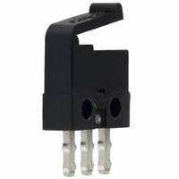
D2MQ-1L Omron, D2MQ-1L Datasheet

D2MQ-1L
Specifications of D2MQ-1L
SW146
Related parts for D2MQ-1L
D2MQ-1L Summary of contents
Page 1
... TR: 3. Terminals None: Straight terminals L: R: Left-angled Right-angled Straight terminals terminals terminals D2MQ-1-TL D2MQ-1-TR D2MQ-1-105 D2MQ-1L-TL D2MQ-1L-TR D2MQ-1L-105 D2MQ-4L-1-L D2MQ-4L-1-R D2MQ-4L-105-1 D2MQ Gold-plated Left-angled terminals Right-angled terminals Left-angled terminals Right-angled terminals Micro load model (Au-plated) Left-angled Right-angled terminals terminals --- --- ...
Page 2
... A max. current t NO 0.5 A max. Minimum applicable load VDC 210 Gold-plated contact type Resistive load operations/min max. 2 {approx. 100G} max. 2 {approx. 30G} max. 10,000 operations min. (30 operations/min) Contact Form Gold-plated contact type Gold plated 0.05 A max. 0.05 A max VDC D2MQ SPDT ...
Page 3
... M1.4 screw holes 4.0 ± 0.1 Electrical Durability (D2MQ-1) 100 Ambient temperature: 20±2°C 70 Ambient humidity: 65±5% Operating frequency: 20 operations/min 50 OT: Full stroke cosφ= 0.1 0.2 0.3 0.4 0.4 Switching current (A) Left-angled Terminals D2MQ 0.5 0.6 Right-angled Terminals 211 ...
Page 4
... D2MQ-1 (Straight Terminals) D2MQ-1-TL (Left-angled terminals) D2MQ-1-TR (Right-angled terminals) D2MQ-1-105 (Straight Terminals) Two, 1.6 Leaf Lever Models D2MQ-1L (Straight Terminals) D2MQ-1L-TL (Left-angled terminals) D2MQ-1L-TR (Right-angled terminals) D2MQ-1L-105 (Straight Terminals) +0.1 Two, 1.6 0 Hinge Leaf Lever Models D2MQ-4L-1 D2MQ-4L-105-1 D2MQ-4L-1-L D2MQ-4L-105-1-L D2MQ-4L-1-R D2MQ-4L-105-1-R +0 ...
Page 5
... When mounting the Switch on a metallic surface, be sure to provide a Separator between the Switch and mounting plate. The Separator must be made of hard material and must be pro- cessed as shown below. Dimensions of Separator 4±0.1 Two 1.6-dia. 2.6 1.2±0.1 mounting holes 0.8 8.2 1 0.25 8.5 D2MQ 213 ...
Page 6
... Design the circuits so that they include appropriate CR circuits to absorb noise or pulse signals. • Use switches with gold-plated contacts for micro loads, which are more resistive to environmental conditions. Switches for Micro Loads If a switch for a general load is used for switching a micro load, it may cause contact failures ...
Page 7
General Information Contact Protective Circuit Apply a contact protective circuit (surge killer) to extend contact du- rability, prevent noise, and suppress the generation of carbide or ni- tric acid due to arc. Be sure to apply the contact protective circuit ...
Page 8
General Information Mechanical Conditions Operating Stroke Setting The setting of stroke is very important for a switch to operate with high reliability. The chart below shows the relationship among operating force, stroke, and contact force. To obtain high reliability from ...
Page 9
... Soldering conditions are even more strict for ultra subminiature switches. Refer to the Precautions for individual models for details. Quick-Connect Terminals Use the specified receptacles to connect to quick-connect termi- nals ...
Page 10
General Information terminals, otherwise the terminal may be deformed or the housing may be damaged. Wiring Work When wiring a switch, check the insulation distance between the switch and the mounting plate. If the insulation distance is insuffi- cient, use ...
Page 11
... Chemical substances have been generated on the contact surface when the switch switches a very low load. Solder flux has penetrated into the switch. Silicon gas exists near the switch. The contacts are separated from each other by vibration or shock. ...


