D2HW-A201D Omron, D2HW-A201D Datasheet - Page 8
D2HW-A201D
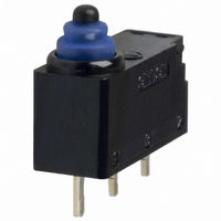
Manufacturer Part Number
D2HW-A201D
Description
SWITCH BASIC SPDT 2A SEALED
Manufacturer
Omron
Series
D2HWr
Type
Snap Actionr
Specifications of D2HW-A201D
Circuit
SPDT
Switch Function
On-Mom
Contact Rating @ Voltage
2A @ 12VDC
Actuator Type
Round (Pin Plunger)
Mounting Type
Through Hole
Termination Style
PC Pin
Operating Force
76gf
Contact Form
SPDT
Contact Rating
1 Amp at 24 Volts
Actuator
Plunger, Pin
Microswitch Type
Ultra Subminiature
Actuator Style
Pin Plunger
Switch Operation
ON-OFF
Operating Force Max
76gf
Contact Voltage Ac Nom
125V
Contact Voltage Dc Nom
42V
Body Style
Subminiature
Current, Rating
1 A
Dielectric Strength
1500 VAC
Ip Rating
IP50
Mounting Hole Size
2.4 mm
Number Of Poles
1
Number Of Positions
2
Operation
On-Off
Termination
Through Hole
Voltage, Rating
24 VDC
Lead Free Status / RoHS Status
Lead free / RoHS Compliant
Lead Free Status / RoHS Status
Lead free / RoHS Compliant, Lead free / RoHS Compliant
Other names
D2HWA201D
SW716
SW716
Available stocks
Company
Part Number
Manufacturer
Quantity
Price


Precautions
Be sure to read the precautions and information common to all Snap Action and Detection Switches, contained in the Technical User’s Guide,
“Snap Action Switches, Technical Information” for correct use.
■ Cautions
Degree of Protection
IEC Publication 529, degree of protection IP67.
Do not use this product in water. Although molded lead wire models
satisfy the test conditions for the standard given below, this test is to
check the ingress of water into the switch enclosure after submerging
the Switch in water for a given time. Satisfying this test condition
does not mean that the Switch can be used in water.
Do not operate the Switch when it is exposed to water spray, or when
water drops adhere to the Switch surface, or during sudden tempera-
ture changes, otherwise water may intrude into the interior of the
Switch due to a suction effect.
Prevent the Switch from coming into contact with oil and chemicals.
Otherwise, damage to or deterioration of Switch materials may
result.
Do not use the Switch in areas where it is exposed to silicon adhe-
sives, oil, or grease, otherwise faulty contact may result due to the
generation of silicon oxide.
Terminal Connection
When soldering the lead wire to the terminal, first insert the lead wire
conductor through the terminal hole and then conduct soldering.
Made sure that the capacity of the soldering iron is 30 W maximum.
Do not take more than 3 s to solder the switch terminal. Improper sol-
dering involving an excessively high temperature or excessive sol-
dering time may deteriorate the characteristics of the Switch.
When soldering the lead wire to the PCB terminal, pay careful atten-
tion so that the flux and solder liquid level does not exceed the PCB
level.
Side-actuated (Cam/Dog) Operation
When using a cam or dog to operate the Switch, factors such as the
operating speed, operating frequency, push-button indentation, and
material and shape of the cam or dog will affect the durability of the
Switch. Confirm performance specifications under actual operation
conditions before using the Switch in applications.
IEC Publication 529, degree of protection IP67.
188
Sealed Subminiature Snap Action Switch
D2HW
■ Correct Use
Mounting
Turn OFF the power supply before mounting or removing the Switch,
wiring, or performing maintenance or inspection. Failure to do so may
result in electric shock or burning.
For M3-screw mounting models, use M3 mounting screws with plane
washers or spring washers to securely mount the Switch. Tighten the
screws to a torque of 0.27 to 0.29 N·m. Exceeding the specified
torque may result in deterioration of the sealing or damage.
For models with posts, secure the posts by thermal caulking or by
pressing into an attached device. When pressed into an attached
device, provide guides on the opposite ends of the posts to ensure
that they do not fall out or rattle.
Mount the Switch onto a flat surface. Mounting on an uneven surface
may cause deformation of the Switch, resulting in faulty operation or
damage.
Operating Body
Use an operating body with low frictional resistance and of a shape
that will not interfere with the sealing rubber, otherwise the plunger
may be damaged or the sealing may deteriorate.
Handling
Do not handle the Switch in a way that may cause damage to the
sealing rubber.
When handling the Switch, ensure that pressure is not applied to the
posts in the directions shown in the following diagram. Also, ensure
that uneven pressure or pressure in a direction other than the operat-
ing direction is not applied to the Actuator as shown in the following
diagram. Otherwise, the post, Actuator, or Switch may be damaged,
or the service life may be reduced.
Wiring Molded Lead Wire Models
When wiring molded lead wire models, ensure that there is no weight
on the wire or that there are no sharp bends near the parts where the
wire is drawn out. Otherwise, damage to the Switch or deterioration
in the sealing may result.
Using Micro Loads
Even when using micro load models within the operating range,
inrush currents or surges may decrease the life expectancy of the
Switch. Therefore, insert a contact protection circuit where neces-
sary.
Related parts for D2HW-A201D
Image
Part Number
Description
Manufacturer
Datasheet
Request
R

Part Number:
Description:
SWITCH BASIC SPDT 2A SEALED
Manufacturer:
Omron
Datasheet:

Part Number:
Description:
SWITCH LEVER SPDT 2A SEALED
Manufacturer:
Omron
Datasheet:

Part Number:
Description:
SWITCH BASIC SPDT 2A SEALED
Manufacturer:
Omron
Datasheet:

Part Number:
Description:
SWITCH LEVER SPDT 2A SEALED
Manufacturer:
Omron
Datasheet:

Part Number:
Description:
SWITCH LEVER SPDT 2A SEALED
Manufacturer:
Omron
Datasheet:

Part Number:
Description:
SWITCH BASIC SPDT 2A SEALED
Manufacturer:
Omron
Datasheet:

Part Number:
Description:
SWITCH ROLL SPDT 2A SEALED
Manufacturer:
Omron
Datasheet:

Part Number:
Description:
SWITCH LEVER SPDT 2A SEALED
Manufacturer:
Omron
Datasheet:

Part Number:
Description:
SWITCH LEVER SPST-NO 2A SEALED
Manufacturer:
Omron
Datasheet:

Part Number:
Description:
SWITCH LEVER SPDT 2A SEALED
Manufacturer:
Omron
Datasheet:

Part Number:
Description:
SWITCH LEVER SPDT 2A SEALED
Manufacturer:
Omron
Datasheet:

Part Number:
Description:
SWITCH LEVER SPDT 2A SEALED
Manufacturer:
Omron
Datasheet:
Part Number:
Description:
SWITCH LEVER SPDT 2A SEALED
Manufacturer:
Omron
Datasheet:

Part Number:
Description:
SWITCH LEVER SPST-NO 2A SEALED
Manufacturer:
Omron
Datasheet:

Part Number:
Description:
SWITCH BASIC SPDT 2A SEALED
Manufacturer:
Omron
Datasheet: