D3C-1210 Omron, D3C-1210 Datasheet - Page 4
D3C-1210
Manufacturer Part Number
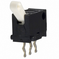
D3C-1210
Description
SWITCH SPDT BASIC 130GF NON-SHRT
Manufacturer
Omron
Series
D3Cr
Type
Detection Switchr
Specifications of D3C-1210
Circuit
SPDT
Switch Function
On-Mom
Contact Rating @ Voltage
0.1A @ 30VDC
Actuator Type
Angled Toggle (Detector)
Mounting Type
Through Hole
Termination Style
PC Pin
Operating Force
130gf
Contact Form
SPDT
Contact Rating
0.1 Amp
Actuator
Lever, Hinge
Contact Configuration
SPDT
Switch Terminals
Through Hole
Contact Current Max
100mA
Contact Voltage Dc Nom
30V
Supply Voltage
30VDC
Circuitry
SPDT
Microswitch Type
Ultra Subminiature
Body Style
Ultra Subminiature
Current, Rating
0.1 A
Dielectric Strength
250 VAC
Mounting Hole Size
1 mm
Number Of Poles
1
Special Features
Detection Switch, Toggle Actuator with Slide Contacts
Termination
Through Hole
Voltage, Rating
30 VDC
Operating Force Max
1.28N
Contact Current Dc Max
100mA
Rohs Compliant
Yes
Actuator Style
Lever
Lead Free Status / RoHS Status
Lead free / RoHS Compliant
Lead Free Status / RoHS Status
Lead free / RoHS Compliant, Lead free / RoHS Compliant
Other names
D3C1210
SW224
SW224


D3C
Precautions
Refer to General Information.
■
Terminal Connection
When soldering the lead wire to the terminal, first bind the lead
wire to the terminal and then apply the solder to the terminal.
Complete soldering within 5 s at a soldering iron temperature of
260°C. Soldering at a temperature exceeding 260°C, soldering for
more than 5 s, or repeated soldering will degrade the Switch char-
acteristics.
When using automatic baths, we recommend soldering at 260±5°C
within 5 seconds.
Make sure that liquid surface of the solder does not flow over the
edge of the board.
It is also recommended that you apply flux guard to the mounting
surface of the Switch.
■
Mounting
Turn OFF the power supply before mounting or removing the
Switch, wiring, or performing maintenance or inspection. Failure
to do so may result in electric shock or burning.
Use M1.6 mounting screws with plane washers or spring washers
to securely mount the Switch. Tighten the screws to a torque of
4.9 to 9.8×10
Mount the Switch onto a flat surface. Mounting on an uneven sur-
face may cause deformation of the Switch, resulting in faulty oper-
ation or breakage in the housing.
Application of Operation Force to the Lever
Apply operation forces to the lever in its operating direction.
Applying operating force to the lever in any other directions will
damage the Switch or cause malfunction.
Mounting Plate
Use materials other than ABS or polycarbonate for the mounting
plate. Since grease is used for the Switch, cracks may be caused
if grease from the Switch comes in contact with such materials.
4
Cat. No. C099-E1-03
Cautions
Correct Use
Incorrect
–2
N·m {0.5 to 1 kgf·cm}.
ALL DIMENSIONS SHOWN ARE IN MILLIMETERS.
To convert millimeters into inches, multiply by 0.03937. To convert grams into ounces, multiply by 0.03527.
Correct
Incorrect
Switch mounting surface
Incorrect
Using Micro Loads
Using a model for ordinary loads to open or close the contact of a
micro load circuit may result in faulty contact. Use models that
operate in the following range. However, even when using micro
load models within the operating range shown below, if inrush
current occurs when the contact is opened or closed, it may
increase contact wear and so decrease durability. Therefore,
insert a contact protection circuit where necessary.
The minimum applicable load is the N-level reference value. This
value indicates the malfunction reference level for the reliability
level of 60% (λ 60). The equation, λ 60 = 0.5×10
indicates that the estimated malfunction rate is less than 1/
2,000,000 operations with a reliability level of 60%.
Inoperable
range
Operating range
Current (mA)
–6
/operations
D3C
Related parts for D3C-1210
Image
Part Number
Description
Manufacturer
Datasheet
Request
R

Part Number:
Description:
SUBMINIATURE BASIC SWITCH
Manufacturer:
Omron
Datasheet:
Part Number:
Description:
SUBMINIATURE BASIC SWITCH
Manufacturer:
Omron
Datasheet:
Part Number:
Description:
SUBMINIATURE BASIC SWITCH
Manufacturer:
Omron
Datasheet:

Part Number:
Description:
G6S-2GLow Signal Relay
Manufacturer:
Omron Corporation
Datasheet:
Part Number:
Description:
Compact, Low-cost, SSR Switching 5 to 20 A
Manufacturer:
Omron Corporation
Datasheet:
Part Number:
Description:
Manufacturer:
Omron Corporation
Datasheet:
Part Number:
Description:
Manufacturer:
Omron Corporation
Datasheet:
Part Number:
Description:
Manufacturer:
Omron Corporation
Datasheet:
Part Number:
Description:
Manufacturer:
Omron Corporation
Datasheet:
Part Number:
Description:
Manufacturer:
Omron Corporation
Datasheet: