SS-01GLP Omron, SS-01GLP Datasheet - Page 2
SS-01GLP
Manufacturer Part Number
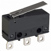
SS-01GLP
Description
SWITCH LEVER SPDT .1A SLDR
Manufacturer
Omron
Series
SSr
Type
Basic Switchesr
Specifications of SS-01GLP
Circuit
SPDT
Switch Function
On-Mom
Contact Rating @ Voltage
0.1A @ 30VDC
Actuator Type
Lever, Straight
Mounting Type
Chassis Mount
Termination Style
Solder Lug
Operating Force
50gf
Contact Form
SPDT
Contact Rating
0.1 Amp at 125 Volts, 0.1 Amp at 30 Volts
Actuator
Lever, Hinge
Post Position
Straight Vertical
Microswitch Type
Subminiature
Actuator Style
Hinge Lever
Operating Force Max
51gf
Contact Voltage Ac Nom
125V
Contact Voltage Dc Nom
30V
Contact Current Max
100mA
Body Style
Subminiature
Current, Rating
0.1 A
Dielectric Strength
1500 VAC
Ip Rating
IP40
Mounting Hole Size
1.6 mm
Number Of Poles
1
Operation
Snap Action
Termination
Solder
Voltage, Rating
30 VDC
Lead Free Status / RoHS Status
Lead free / RoHS Compliant
Lead Free Status / RoHS Status
Lead free / RoHS Compliant, Lead free / RoHS Compliant
Other names
SS01GLP
SW776
SW776


Specifications
■ Characteristics
Note: 1. The data given above are initial values.
■ Ratings
Note: The electrical rating applies under the following test conditions:
■ Approved Standards
UL Recognized (File No. E41515)
CSA Certified (UL approval)
EN61058-1 - - VDE approval
(File No. 40008425)
Testing conditions: 5E4 (50,000 operations), T55 (0°C to 55°C)
Note: The rated values approved by each of the safety standards
104
Operating speed
Operating frequency
Insulation resistance
Contact resistance
Dielectric strength (See note 2)
Vibration resistance (See note 3)
Shock resistance (See note 3)
Degree of protection
Degree of protection against electrical shock
Proof tracking index (PTI)
Ambient operating temperature
Ambient operating humidity
Life expectancy
Weight
125 VAC
30 VDC
Rated Voltage
125 VAC
30 VDC
Rated Voltage
125 VAC
30 VDC
2. The dielectric strength shown in the table indicates a value for models with a Separator.
3. For the pin plunger models, the above values apply for both the free position and total travel position. For the lever models, the values
(e.g. UL, CSA) may be different from the performance charac-
teristics individually defined in this catalog.
Ambient Temperature = 20±2°C, Ambient Humidity = 65±5%, Operating frequency = 30 operations/minute
apply at the total travel position. Contact opening or closing time is within 1 ms.
Rated voltage
Subminiature Basic Switch
SS-3P
SS-3P
3 A
3 A
3 A
3 A
Model
Item
SS-01P
SS-01P
0.1 A
0.1 A
0.1 A
0.1 A
SS-P
0.1 mm to 1 m/s (for pin plunger models)
Mechanical: 300 operations/min
Electrical: 30 operations/min
100 MΩ min. (at 500 VDC)
SS-3P: 50 mΩ max.
SS-01P: 100 mΩ max.
1,000 VAC, 50/60 Hz for 1 min between terminals of the same polarities
1,500 VAC, 50/60 Hz for 1 min between current-carrying metal parts and ground, and
between each terminal and non-current-carrying metal parts
Malfunction: 10 to 55 Hz, 1.5-mm double amplitude
Destruction: 1,000 m/s
Malfunction: 300 m/s
IEC IP40
Class I
175
−25°C to 85°C (at 60% RH max.) with no icing
85% max. (for 5°C to 35°C)
Mechanical: 1,000,000 operations min. (60 operations/min)
Electrical: SS-3P:
Approx. 1.6 g (for pin plunger models)
3 A
3 A
SS-01P: 200,000 operations min. (20 operations/min)
■ Contact Specifications
Note: Minimum applicable loads are indicated by N standard refer-
Specification
Material
Gap (standard value)
Minimum applicable
load (see note)
70,000 operations min. (20 operations/min, 125 VAC)
100,000 operations min. (20 operations/min, 30 VDC)
SS-3P
2
(approx. 30 G) max.
2
(approx. 100 G) max.
ence values. This value represents the failure rate at a 60%
(λ
The equation
rate of 1/2,000,000 operations can be expected at a reliability
level of 60%
60
Item
) reliability level (JIS C5003).
Resistive load
λ
60
=0.5 x 10
0.1 A
0.1 A
160 mA at 5 VDC
Silver alloy
SS-3P
-6
Rivet
/ operations indicates that a failure
SS-01P
0.5 mm
1 mA at 5 VDC
Gold alloy
Crossbar
SS-01P
Related parts for SS-01GLP
Image
Part Number
Description
Manufacturer
Datasheet
Request
R

Part Number:
Description:
SWITCH BASIC SPDT .1A 150GF SLD
Manufacturer:
Omron
Datasheet:

Part Number:
Description:
SUBMINIATURE BASIC SWITCH
Manufacturer:
Omron
Datasheet:

Part Number:
Description:
PIN PLUNGER SPDT 1.8OZ/.1AMP
Manufacturer:
Omron
Datasheet:

Part Number:
Description:
SW SUBMINI SPDT .1A PIN PLNGR
Manufacturer:
Omron
Datasheet:
Part Number:
Description:
SW SUBMINI SPST-NO .1A PIN PLNGR
Manufacturer:
Omron
Datasheet:
Part Number:
Description:
SUBMINIATURE BASIC SWITCH
Manufacturer:
Omron
Datasheet:
Part Number:
Description:
Subminiature Basic Switch
Manufacturer:
Omron
Datasheet:
Part Number:
Description:
SUBMINIATURE BASIC SWITCH
Manufacturer:
Omron
Datasheet:
Part Number:
Description:
SUBMINIATURE BASIC SWITCH
Manufacturer:
Omron
Datasheet:
Part Number:
Description:
Subminiature Basic Switch
Manufacturer:
Omron
Datasheet:
Part Number:
Description:
SUBMINIATURE BASIC SWITCH
Manufacturer:
Omron
Datasheet:
Part Number:
Description:
SUBMINIATURE BASIC SWITCH
Manufacturer:
Omron
Datasheet:
Part Number:
Description:
SUBMINIATURE BASIC SWITCH
Manufacturer:
Omron
Datasheet:
Part Number:
Description:
SUBMINIATURE BASIC SWITCH
Manufacturer:
Omron
Datasheet:
Part Number:
Description:
Basic / Snap Action / Limit Switches HINGE LEVER SOLDER SNAP-ACTION
Manufacturer:
Omron