SS12SDP2LF NKK Switches, SS12SDP2LF Datasheet - Page 2
SS12SDP2LF
Manufacturer Part Number
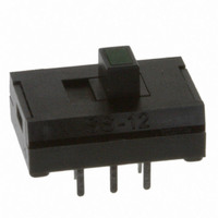
SS12SDP2LF
Description
SW SLIDE SPDT GRN ILLUM 0.1A PCB
Manufacturer
NKK Switches
Series
SSr
Specifications of SS12SDP2LF
Circuit
SPDT
Switch Function
On-On
Contact Rating @ Voltage
0.1A @ 30VDC
Actuator Type
Illuminated
Mounting Type
Through Hole
Orientation
Vertical
Termination Style
PC Pin
Contact Form
SPDT
Contact Rating
0.1 Amp at 30 Volts
Mounting Style
Through Hole
Illumination
Not Illuminated
Illumination Color
Green
Travel
2 mm
Lead Free Status / RoHS Status
Lead free / RoHS Compliant


H
General
Series SS
Electrical Capacity (Resistive Load)
Other Ratings
Materials & Finishes
Environmental Data
PCB Processing
Standards & Certifications
H50
Operating Temp Range:
Insulation Resistance:
Movable Contactor:
Contact Resistance:
Dielectric Strength:
Mechanical Life:
Contact Timing:
Electrical Life:
Interior Base:
Power Level:
Upper Case:
Lower Case:
Total Travel:
Soldering:
Terminals:
Vibration:
Humidity:
Actuator:
Cleaning:
Shock:
Specifications
0.1A @ 30V DC
20 milliohms maximum
100 megohms minimum @ 500V DC
500V AC minimum 1 minute minimum
10,000 operations minimum
10,000 operations minimum
Shorting (make-before-break)
.079” (2.0mm)
Polyacetal
Polyacetal
Glass fiber reinforced polyester
Phosphor bronze with silver plating
Phenolic resin (thermoset)
Brass with silver plating over copper plating
–15°C through +60°C (+5°F through +140°F)
90 ~ 95% humidity for 96 hours @ 40°C (104°F)
10 ~ 55Hz with peak-to-peak amplitude of 1.5mm traversing the frequency range
& returning in 1 minute; 3 right angled directions for 2 hours
50G (490m/s
Wave Soldering: For non-supported through-hole, see Profile B in Supplement section.
For supported through-hole, 5 seconds maximum @ 250°C maximum.
Manual Soldering: See Profile B in Supplement section.
These devices are not process sealed. Hand clean locally using alcohol based solution.
The SS series devices have not been tested for UL recognition and CSA certification.
These switches are designed for use in a low-voltage, low-current circuit.
When used as intended in a low-voltage, low-current circuit, the results do not produce
hazardous energy.
2
) acceleration (tested in 6 right angled directions, with 5 shocks in each direction)
www.nkk.com
Ultra-Miniature Illuminated Slides
Related parts for SS12SDP2LF
Image
Part Number
Description
Manufacturer
Datasheet
Request
R

Part Number:
Description:
DIODE SCHOTTKY 1A 20V SMA
Manufacturer:
Fairchild Semiconductor
Datasheet:

Part Number:
Description:
DIODE SCHOTTKY 1A 20V SMA
Manufacturer:
Vishay
Datasheet:
Part Number:
Description:
RECTIFIER SCHOTTKY 1A20V SMA
Manufacturer:
Vishay
Datasheet:
Part Number:
Description:
DIODE SCHOTTKY 1A 20V SMA
Manufacturer:
Vishay
Datasheet:
Part Number:
Description:
RECTIFIER DIODE,SCHOTTKY,20V V(RRM),DO-214AC / SMA
Manufacturer:
Vishay
Datasheet:

Part Number:
Description:
SCHOTTKY RECTIFIER, 1A 20V DO-214AC
Manufacturer:
Vishay
Datasheet:

Part Number:
Description:
Schottky (Diodes & Rectifiers) 20 Volt 1.0 Amp 40 Amp IFSM
Manufacturer:
Vishay
Datasheet:
Part Number:
Description:
Schottky (Diodes & Rectifiers) 20 Volt 1.0 Amp 40 Amp IFSM
Manufacturer:
Vishay
Datasheet:
Part Number:
Description:
Schottky (Diodes & Rectifiers) 20 Volt 1.0 Amp 40 Amp IFSM
Manufacturer:
Vishay
Datasheet:
Part Number:
Description:
Schottky (Diodes & Rectifiers) 20 Volt 1.0 Amp 40 Amp IFSM
Manufacturer:
Vishay
Datasheet:
Part Number:
Description:
Schottky (Diodes & Rectifiers) 20 Volt 1.0 Amp 40 Amp IFSM
Manufacturer:
Vishay
Datasheet:
Part Number:
Description:
Schottky (Diodes & Rectifiers) 20 Volt 1.0 Amp 40 Amp IFSM
Manufacturer:
Vishay
Datasheet:
Part Number:
Description:
Schottky (Diodes & Rectifiers) 20 Volt 1.0 Amp 40 Amp IFSM
Manufacturer:
Vishay
Datasheet:
Part Number:
Description:
Schottky (Diodes & Rectifiers) 1.0 Amp 20 Volt
Manufacturer:
Vishay
Datasheet:

Part Number:
Description:
SMD Schottky Barrier Rectifier
Manufacturer:
Comchip Technology Corp.