50DP60-01-2-AJN Grayhill Inc, 50DP60-01-2-AJN Datasheet - Page 3
50DP60-01-2-AJN
Manufacturer Part Number
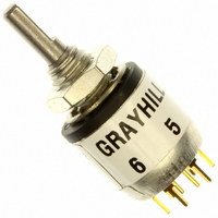
50DP60-01-2-AJN
Description
SW ROTARY DP 200MA 0.5" PC MNT
Manufacturer
Grayhill Inc
Series
50r
Datasheet
1.50D36-01-1-AJN.pdf
(7 pages)
Specifications of 50DP60-01-2-AJN
Angle Of Throw
60°
Number Of Positions
2 ~ 3
Number Of Decks
1
Number Of Poles Per Deck
2
Circuit Per Deck
DP3T
Contact Rating @ Voltage
0.2A @ 28VDC
Actuator Type
Flatted (3.17mm dia)
Mounting Type
Panel, PCB Through Hole
Termination Style
PC Pin
Orientation
Vertical
No. Of Poles
2
No. Of Switch Positions
3
Contact Current Ac Max
150mA
Contact Current Dc Max
200mA
Contact Voltage Ac Max
220V
Contact Voltage Dc Max
28V
Circuitry
DP3T
Lead Free Status / RoHS Status
Lead free / RoHS Compliant
Other names
50DP60-01-2-AJN


SPECIFICATIONS
SPECIFICATIONS: Other
PROCESS SEAlEd–Style T
Switch can be mounted on PC board with other
components and subjected to wave soldering
and conventional board cleaning techniques. No
secondary wiring or soldering is necessary.
Bushing is o‑ring sealed; epoxy potting seals the
terminals and the rear of the switch. Designed
for PC assembly, this sealing technique can also
be applied to solder lug terminal switches. A
bushing to panel seal can also be added to the
process sealed versions. Military qualified ver‑
sions are available, see ordering information.
Rotary
Military Qualification
The dimensions for qualified switches are
the same as those indicated in the drawings
of standard switches. Switches with standard
variations, such as shaft and bushing length,
which do not affect switch performance, can be
marked as qualified product. Contact Grayhill
for complete information on variations.
36°, 45°, 60°, 90° (Series 50): The C and M
style switches are qualified to MIL‑S‑3786/20.
They include the following:
Series 50 qualified switches may be ordered
by the ‘M’ number or by the Grayhill part
number.
30° (Series 51): The C and M style switches
are qualified to MIL‑S‑3786/35. They include
the following:
Series 51 qualified switches may be ordered
by the ‘M’ number or by the Grayhill part
number.
Additional Characteristics
Contact Type and Forces: Shorting or non‑
shorting wiping contacts with over 80 grams
of contact force.
Shaft Flat Orientation: Flat opposite contacting
position of pole number one (see circuit
diagrams).
Terminals: Switches have the full circle of
terminals, regardless of number of active
position.
Stop Strength: 7.5 pound‑inches minimum
Rotational Torque: 8–24 ounce‑inches,
depending on the number of poles.
6
Solder lug or PC terminals
With or without panel seal
Solder lug or PC terminals
With or without panel seal
Grayhill, Inc. • 561 Hillgrove Avenue • LaGrange, Illinois
Single Deck Rotary Switches
Electrical Ratings
life Expectancy: With the limiting criteria stated
here, the Series 50 and 51 with non‑shorting
contacts will switch the following loads at
atmospheric and reduced pressures for 25,000
cycles of operations. One cycle is 360° rotation
clockwise and 360° return.
At 85°C, atmospheric pressure
At 25°C, reduced pressure (70,000 feet)
Materials and Finishes
Switch Base: Thermoset
detent Rotor: Nylon
Shaft, Stop Blades, Stop Arm, Thrust washer,
and Retaining Ring: Stainless steel
detent Balls: Steel, nickel‑plated
Bushing: Zinc, tin‑zinc plated
Detent and Contact Springs: Stainless steel
Common Ring: Brass, gold‑plated over silver
plate.
Terminals: Brass, gold‑plated over silver plate
and nickel plate
Rotor Contact: Precious metal alloy, gold‑
plated
1/4" SHAFT: Style K
200 mA,
150 mA,
30 mA,
100 mA,
75 mA,
200 mA,
150 mA,
75 mA,
CIRCLE SHOWING
HOLE TO BE CUT
DIMENSIONS OF
IN PANEL.
115 Vac resistive
220 Vac lamp load
115 Vac resistive
220 Vac resistive
60525-5997 • USA • Phone: 708-354-1040 • Fax: 708-354-2820 • www.grayhill.com
28 Vdc resistive
28 Vdc inductive
28 Vdc lamp load
28 Vdc resistive
.219
±.004
0.208
1/8"Shaft
.340
±.005
Ø0.254
POS. 1
.250
.250
±.015
.375
±.015
+.001
-.002
.250
±.015
"E" Style
Contact Resistance: 20 milliohms maximum,
(10 milliohms initially).
Insulation Resistance: 1,000 Mohms
minimum between mutually insulated parts.
Voltage Breakdown: 600 Vac minimum
between mutually insulated parts at standard
atmospheric pressure.
life Expectancy: Listed for the voltage source
and make and break current levels. Contact
Grayhill for more information if any of the
following is true: the life limiting criteria are
more critical than those listed; longer operation
is required; a larger make and break current is
required; the operating environment includes
elevated temperatures or reduced pressures.
Contact Carry Rating: Switch will carry
6 amperes continuously with a maximum
contact temperature rise of 20°C.
Panel Seal: Silicone rubber
Shaft Seal: Fluorosilicone
Mounting Nuts: Brass, tin‑zinc plated
Mounting Hardware: One mounting nut .089"
thick by .375" across flats and one internal tooth
lockwasher are supplied with the switch.
Maximum Mounting Torque: 15in‑lbs
Ø0.280
0.240
POS. 1
3/8-32 UNEF-2A
THREAD
"K" Style
"K" Style
0.350
POS. 1
Ø0.380
Ø0.380
0.350
POS. 1
Related parts for 50DP60-01-2-AJN
Image
Part Number
Description
Manufacturer
Datasheet
Request
R

Part Number:
Description:
SW ROTARY SP 200MA 0.5" PC MNT
Manufacturer:
Grayhill Inc
Datasheet:

Part Number:
Description:
Encoder; 32pos; custom switching; sealed; continous rotation;
Manufacturer:
Grayhill Inc
Part Number:
Description:
50EPT90-01-1-04N-C SINGLE DECK ROTARY 0.5(12.7mm)DIA,200mA,Continuous
Manufacturer:
Grayhill Inc
Part Number:
Description:
Rotary Switch seal adj.stop 36� 1deck 1pol/deck 56BSD36-01PAJN -bulk
Manufacturer:
Grayhill Inc
Part Number:
Description:
Rotary Switch, Screwdriver slot shaft, shaft/panel seal, PC mount, 30°
Manufacturer:
Grayhill Inc
Part Number:
Description:
Encoder MODIFIED SPECIAL VERSION OF GRH'S 60A18-4-040C
Manufacturer:
Grayhill Inc
Part Number:
Description:
GRAYHILL,SERIES 71,ROTARY SWITCH,1/8 SHAFT,30DEGREE,DECK,1 POLE/DECK,12POSITION/POLE,NON-SHORTING,CONTINUOUS .
Manufacturer:
Grayhill Inc
Part Number:
Description:
Keypad Legend, INC, Standard Font, White On Black
Manufacturer:
Grayhill Inc

Part Number:
Description:
SWITCH DIP EXTENDED UNSEAL 4POS
Manufacturer:
Grayhill Inc
Datasheet:

Part Number:
Description:
SWITCH DIP EXT RCKR UNSEALD 4POS
Manufacturer:
Grayhill Inc
Datasheet:
Part Number:
Description:
SWITCH DIP EXTENDED SEALED 4POS
Manufacturer:
Grayhill Inc
Datasheet:

Part Number:
Description:
SWITCH DIP RECESSED SEALED 4POS
Manufacturer:
Grayhill Inc
Datasheet: