MA00L3NCGD C&K Components, MA00L3NCGD Datasheet - Page 5
MA00L3NCGD
Manufacturer Part Number
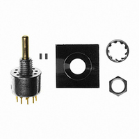
MA00L3NCGD
Description
SWITCH ROTARY SP 10POS 6A PCB
Manufacturer
C&K Components
Series
Mr
Datasheet
1.638101000.pdf
(5 pages)
Specifications of MA00L3NCGD
Number Of Positions
10
Number Of Decks
1
Number Of Poles Per Deck
1
Circuit Per Deck
SP10T
Contact Rating @ Voltage
0.25A @ 125VAC
Actuator Type
Round (3.17mm dia)
Mounting Type
Panel, PCB Through Hole
Termination Style
PC Pin
Orientation
Vertical
Angle Of Throw
36°
Index Angle
36 deg
Contact Style
Non Shorting
Contact Form
SP
Contact Material
Gold over Silver
Contact Plating
Gold
Voltage Rating
125 Volts
Current Rating
250 mAmps
Contact Rating
250 mAmps at 125 VoltsAC, 28 VoltsDC
Voltage Rating Ac
125 Volts
Voltage Rating Dc
28 Volts
Lead Free Status / RoHS Status
Lead free / RoHS Compliant
Other names
*MA00L3NCGD
CKN9878
CKN9878


M Series
Half-inch Rotary Switches
SEAL
D
F
NO EPOXY SEAL
SPLASHPROOF SHAFT AND PANEL SEAL
IP67 approved
Setting Stops With Stop Pins
MA00, MB00, MC00 & MD00 Models Only:
The number of switch positions or stops are adjustable by means of stop pins provided with each switch. Switches are normally
shipped with stop pins and hardware in bulk, not installed. Without stop pins, switches have full 360º rotation and no stops.
Note that all two pole models begin to repeat when actuated 180º or more.
To set stops, refer to figures 1 & 2. Orient switch so that terminal no. 1 is as shown. Turn actuator to position 1, using flats on
bushing and terminal no. 1 as reference. Install CCW stop pin in hole designated ‘X’. Install second stop pin in hole number
corresponding to the number of positions desired. Note that two pole models will begin to repeat when actuated 180º or more.
To retain stop pins, use adhesive mylar washer included; see figure 3.
All models except MX00 models have number of switch positions or stops pre-set at factory and are not adjustable.
Hardware:
Two stop pins, mounting nut, and lockwasher supplied standard.
P/N 537100000
K
36º Indexing Models
30º Indexing Models
Top View
Top View
P/N 537202000
Fig. 1
Fig. 2
Fig. 3
Setting Stops With Stop Rings
ME00, MF00, MG00 & MH00 Models Only:
The number of switch positions or stops are adjustable by means of stop rings provided with each switch. These models are
normally shipped with stop rings and hardware in bulk, not installed. Without stop rings, switches have full 360º rotation and no
stops. Note that all two pole models begin to repeat when actuated 180º or more.
To set stops refer to figures 4 & 5. Orient switch so that terminal no. 1 is as shown. Turn actuator to pos. 1 using flats on bushing
and terminal no. 1 as reference. See figure 6 and install inner stop ring with short tab in hole designated ‘X’. Install outer
stop ring with long tab in hole number corresponding to the number of positions desired. Note that all two pole models begin to
repeat when actuated 180º or more. Use mounting nut and lockwasher to retain stop rings.
All MEXX, MFXX, MGXX & MHXX Models (Except MX00 models):
Number of switch positions or stops are preset at factory, but are user adjustable.
Hardware:
Two stop rings, mounting nut and lockwasher supplied standard.
36º Indexing Models
30º Indexing Models
Top View
Top View
Fig. 4
Fig. 5
Fig. 6
Dimensions are shown: mm
Specifications and dimensions subject to change
www.ck-components.com
K–17
Related parts for MA00L3NCGD
Image
Part Number
Description
Manufacturer
Datasheet
Request
R

Part Number:
Description:
Rotary Switches 4P 3 POS ROTARY SW
Manufacturer:
C&K Components
Part Number:
Description:
ANALOG ROCKER C&K DELTATECH
Manufacturer:
C&K Components
Part Number:
Description:
QUARDANT MODUL C&K DELTATECH
Manufacturer:
C&K Components
Datasheet:
Part Number:
Description:
TOGGLE,THT-PC,SPDT,ON-OFF-ON,ACT-DXL:6.09X17.15MM,BUSH-THREADED,AU
Manufacturer:
C&K Components
Part Number:
Description:
SMARTCARD CONNECTOR *Y1112-2013AP LFT
Manufacturer:
C&K Components
Part Number:
Description:
Connector reel; SIM card; 6 contacts; hinged; no switch lock
Manufacturer:
C&K Components
Part Number:
Description:
CCM03-MKII SmartCard Conn for SIM/SAM cards, 6-contacts hinged 1k reel
Manufacturer:
C&K Components