44D30-03-1-AJN Grayhill Inc, 44D30-03-1-AJN Datasheet - Page 3
44D30-03-1-AJN
Manufacturer Part Number
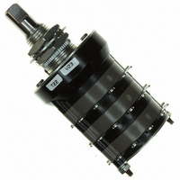
44D30-03-1-AJN
Description
SW RTRY 3 DECK 1AMP 1" MIL STYL
Manufacturer
Grayhill Inc
Series
44r
Type
Rotaryr
Specifications of 44D30-03-1-AJN
Angle Of Throw
30°
Number Of Positions
2 ~ 12
Number Of Decks
3
Number Of Poles Per Deck
1
Circuit Per Deck
SP12T
Contact Rating @ Voltage
1A @ 115VAC
Actuator Type
Flatted (6.35mm dia)
Mounting Type
Panel Mount
Termination Style
Solder Lug
Orientation
Vertical
No. Of Poles
1
No. Of Switch Positions
12
Contact Current Ac Max
1A
Contact Current Dc Max
1A
Contact Voltage Ac Max
115V
Contact Voltage Dc Max
115V
Brand/series
44 Series
Current, Rating
1 A
Dielectric Strength
1000 VAC
Material, Contact
Silver Alloy (Rotor)
Mechanical Life
100000 Cycles of Operations
Number Of Poles
1
Standards
UL Recognized
Termination
Solder
Voltage, Rating
115 V
Circuitry
SP12T
Rohs Compliant
Yes
Lead Free Status / RoHS Status
Lead free / RoHS Compliant
Lead Free Status / RoHS Status
Lead free / RoHS Compliant, Lead free / RoHS Compliant
Other names
GH7334


SERIES 42
1" Diameter, 1 Amp, PC Mount
DIMENSIONS
ADJUSTABLE STOP SWITCHES: Series 42 and 44
FEATURES
• Satisfies High Current Board Level
• 36° Angle of Throw Permits up to
• UL Recognized Versions
CIRCUIT DIAGRAM: PC Mount
Rotary
The standard and UL recognized switches are
also available with adjustable stops. Two
removable stop washers allow you to limit the
number of switch positions as needed. A knurled
nut is supplied to secure the washers if desired.
These switches have no bushing keyway. All
other dimensions, ratings and characteristics
are the same as the standard fixed stop styles.
Although not military qualified, the adjustable
styles are useful in military equipment
prototypes. However, when submitting the
equipment for government approval, the fixed
stop qualified style should be substituted.
Termination
One-sided termination is standard for switches with 2 to 5
positions per pole. Two-sided termination is standard for
switches with 6 thru 10 positions per pole.
6 thru 10 positions
per
terminals from one
side of switch are
available on special
order. See Special
Options, page F-10
or contact Grayhill.
Applications
Ten Positions
Standard Style
24
.219
± .005
(5,56
± 0,13)
Grayhill part number and date code marked on detent cover label. Customer part
number marked on request. UL recognized marking as required.
Switch is Viewed From Shaft End
Note: All common terminals are located above
pole
C L
and Shown in Position No. 1
OF BUSHING
KEYWAY
Grayhill, Inc. • 561 Hillgrove Avenue • LaGrange, Illinois
and
TERMINAL DIMENSIONS AT THIS
POINT ARE .050 ± .005 (1,27 ± 0,13)
WIDE BY .020 ± .003 (0,51 ± 0,08) THICK
base terminals as shown.
(25,4 ± 0,25)
1.000 ± .010
DIA.
In inches (and millimeters)
8
9
7
ONE POLE
10
6
Multi-Deck Rotary Switches
1
5
(19,05 ± 0,25)
2
4
.750 ± .010
3
.375 ± .015
(9,53 ± 0,38) TYP.
C L OF
C1
TYP.
BUSHING
KEYWAY
(15,24 ± 0,79)
(11,10 ± 0,51)
.600 ± .031
(6,35 ± 0,51)
.437 ± .020
.250 ± .020
.250 + .001 –.002
(6,35 + 0,03 –0,05)
DIA.
PC BOARD MOUNTING PATTERN
Equivalent Styles
For style 42A36, use 42D36,
For style 44A30, use 44D30
For style 42M36, use 42D36 initially
For style 44M30, use 44D30 initially
For style 42U36, use 42UD36
For style 44U30, use 44UD30
(19,05)
.750
TYP.
(9,53)
.375
TYP.
Series 42
C L
.174 (4,42)
OF FRONT SUPPORT
PLATE MOUNTING
HOLES
(12,7)
.500
TYP.
(12,50)
Shown for a two deck switch
.492
(6,35)
60525-5997 • USA • Phone: 708-354-1040 • Fax: 708-354-2820 • www.grayhill.com
.250
TYP.
TYP.
Front Views
.174
± .010
(4,42
± 0,25)
DIM. A + .046 – .020
(+1,17 –0,00)
INTEGRAL ASSEMBLY NUT,
DO NOT REMOVE
BUSHING KEYWAY
.066 ± .002 (1,68 ± 0,05) WIDE BY
.036 ± .003 (0,91 ± 0,08) DEEP
FROM A .375 (9,53) DIA.
3/8-32 UNEF-2A THREAD
(MTG. HOLE=3/8 DIA. MIN.)
C
L C L C L
.174 (4,42) TYP.
Series 44
COMMON LUG
C L COMMON
C L OF REAR
C L OF BASE
.110 (2,79)
TERMINAL
MOUNTING
HOLES
SUPPORT
PLATE
MOUNTING
HOLES
TERMINAL
MOUNTING
HOLES
.830
± .010
(21,08
± 0,25)
.174 ± .010
(4,42 ± 0,25)
#1 THREAD
DIM. B REF.
STUD
PROJECTION
SHAFT AND PANEL SEAL: Srs. 42 & 44
The Series 42/44 Styles, which include the letter "S" with the
exception of style "HS", are watertight sealed to the mounting
panel by utilizing the panel seal kit. These switches are built
with a front plate that does not have a non-turn tab. The
panel seal kit consists of a grooved hex nut, a keyed washer
and a keyed panel seal. The grooved hex nut is assembled
to the switch bushing. The keyed washer is slid down the
bushing slot and seated into the hex nut groove. The seal
is likewise assembled to the bushing and hex nut. The
keyed washer is required to provide seal integrity in the
bushing slot. When assembled to the panel, the grooved
nut, backing washer and seal require the same space as a
normal mounting nut. Hence, the seal kit does not alter the
dimensions. Panel seal kit includes a non-turn washer to be
used into a blind hole in the back panel. For panel seal kit
part dimensions, see Accessories. Style "HS" switches use
a similar sealing method, except the integral assembly nut
retains the panel seal. All sealed style switches are provided
with a shaft to bushing internal seal.
Standard Style
USE OF KNURLED
NUT IS OPTIONAL
(37,34 ± 0,51)
1.470 ± .020
TYP.
.786 ± .010
(19,96 ± 0,25)
DIA.
ADJUSTABLE STOP
WASHERS
(12,7 ± 0,38)
.500 ± .015
.187 ± .015
(4,75 ± 0,38) TYP.
.250 ± .015
(6,35 ± 0,38) TYP.
.735 ± .010
(18,67 ± 0,25) TYP.
TYP.
Related parts for 44D30-03-1-AJN
Image
Part Number
Description
Manufacturer
Datasheet
Request
R


Part Number:
Description:
Rotary Switch, Standard, Adjustable Stops, 30°
Manufacturer:
Grayhill Inc
Datasheet:

Part Number:
Description:
Rotary Switch, Standard, Adjustable Stops, 30°
Manufacturer:
Grayhill Inc
Datasheet:
Part Number:
Description:
Rotary Switch, Standard, Adjustable Stops, 30°
Manufacturer:
Grayhill Inc
Datasheet:
Part Number:
Description:
Rotary Switch, Standard, Adjustable Stops, 30°
Manufacturer:
Grayhill Inc
Part Number:
Description:
Rotary Switch, Standard, Adjustable Stops, 30°
Manufacturer:
Grayhill Inc
Part Number:
Description:
Rotary Switch, Standard, Adjustable Stops, 30°
Manufacturer:
Grayhill Inc
Part Number:
Description:
44D30-01-4-AJS Table Stops, 30°
Manufacturer:
Grayhill Inc
Datasheet:
Part Number:
Description:
44D30-07-1-AJS Table Stops, 30°
Manufacturer:
Grayhill Inc
Datasheet:
Part Number:
Description:
44D30-10-1-AJS Table Stops, 30°
Manufacturer:
Grayhill Inc
Datasheet:
Part Number:
Description:
44D30-11-2-AJN Table Stops, 30°
Manufacturer:
Grayhill Inc
Datasheet:
Part Number:
Description:
Rotary Switch, Standard, Adjustable Stops, 30°
Manufacturer:
Grayhill Inc

Part Number:
Description:
Rotary Switch, Standard, Adjustable Stops, 30°
Manufacturer:
Grayhill Inc
Datasheet: