71AD36-01-1-AJN Grayhill Inc, 71AD36-01-1-AJN Datasheet - Page 8
71AD36-01-1-AJN
Manufacturer Part Number
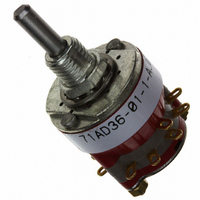
71AD36-01-1-AJN
Description
SW ROTARY SP 1/8" SLDR TRM
Manufacturer
Grayhill Inc
Series
71r
Datasheet
1.71AD36-01-1-AJN.pdf
(14 pages)
Specifications of 71AD36-01-1-AJN
Angle Of Throw
36°
Number Of Positions
2 ~ 10
Number Of Decks
1
Number Of Poles Per Deck
1
Circuit Per Deck
SP10T
Contact Rating @ Voltage
0.25A @ 28VDC
Actuator Type
Flatted (3.17mm dia)
Mounting Type
Panel Mount
Termination Style
Solder Lug
Orientation
Vertical
No. Of Poles
1
No. Of Switch Positions
10
Contact Current Ac Max
300mA
Contact Voltage Ac Max
115V
Contact Voltage Dc Max
30V
Circuitry
SP10T
No. Of Decks
1
Contact Current Max
250mA
Rohs Compliant
Yes
Lead Free Status / RoHS Status
Lead free / RoHS Compliant
Other names
71AD36-01-1-AJN
GH7359
Q2941486
GH7359
Q2941486


DIMENSIONS
CIRCUIT DIAGRAMS: PC Mount Terminals
PC Mount: Style CF
12
SEE SOLDER LUG
VERSION FOR
SHAFT FLATS AND
DIMENSIONS
11
Grayhill part number and date code marked on detent cover label. Customer part number marked on request.
10 9 8 7 6 5 4 3
.725 (36°) ± .015
(17,45 ± 0,38)
(22,23, 18,42
.687 ± .015
.875 (30°)
Sec. A
.020 ± .003
(0,51 ± 0,08)
TYP.
± 0,38)
ONE POLE
DIA.
1
2
3
1
2
3
1
2
3
For additional dimensions and references
for shafts, flat orientation and bushing
keyway, see drawings for styles 71AF and
71BF.
No. of Decks
In inches (and millimeters)
Sec. B
1
1
1
2
2
2
3
3
3
30° Angle of Throw
POSITION
NO. 1
2
C1
C
1
L
Dimension A
1.415 (35,94)
1.633 (41,49)
2.131 (54,13)
1.633 (41,49)
2.131 (54,13)
2.349 (59,66)
2.131 (54,13)
2.349 (59,66)
2.567 (65,20)
OF BUSHING
KEYWAY OR
FLATS
.125 + .001
–.002 DIA.
(3,18 + 0,25
–0,05)
.250 ± .020
(6,35 ± 0,05)
.375 ± .020
(9,53 ± 0,05)
Switch is Viewed From Shaft End and Shown in Position No. 1.
12
.250 + .001
–.002
(6,35 + 0,03
–0,05)
DIA.
11
Dimension B
Note: All common terminals are located above base terminals as shown.
.032 (0,81)
.032 (0,81)
.312 (7,92)
.032 (0,81)
.312 (7,92)
.312 (7,92)
.312 (7,92)
.312 (7,92)
.312 (7,92)
10 9 8 7 6 5 4 3 2 1
C2
3/8-32 UNEF-2A
THREAD
.312 ± .020
(7,92 ± 0,51)
TWO POLE
.412 ± .010
(10,46 ± 0,25)
TYP.
Approx.
Weight
Grams
24
26
28
26
28
30
28
30
32
C1
C L
.015
± .002
(0,38
± 0,05)
SECTION
SECTION A
COMMON
DECK 1
For layout of printed circuit
board,
illustrated on page J-36.
A
C L
STUD PROJECTION
C
L
(16,66)
DIM. A
C
.656
L
.110 ± .010
(2,79 ± 0,25)
TYP.
DIM. B REF.
SECTION B
COMMON
10 9 8 7 6 5 4 3 2 1
see
SECTION
DECK 1
C
L
B
ONE POLE
SEE NOTE
BELOW
diagrams
.562
± .015
(14,27
± 0,38)
See pages J-39 through J-44 for specifications,
accessories and ordering information.
36° Angle of Throw
C1
C
L
OF BUSHING
KEYWAY OR
FLATS
(3,96 ± 0,25)
(3,96 ± 0,25)
.156 ± .010
Note: Common location for a Single Pole Per
.156 ± .010
TYP.
30° and 36° Angle of Throw may be
interposed on either shaft diameter.
TYP.
SEE
NOTE
SEE
NOTE
(1,91 ± 0,13)
Deck Switch. For common location on
multipole switches see circuit diagrams.
(1,91 ± 0,13)
.075 ± .005
.075 ± .005
36° Angle of Throw
30° Angle of Throw
10 9 8 7 6 5 4 3 2 1
Rear Views
TYP.
TYP.
C2
(12,7 ± 0,38)
(12,7 ± 0,38)
.500 ± .015
.500 ± .015
TWO POLE
DIA.
DIA.
C L
C L
C L
C L
.125 ± .010
(3,18 ± 0,25)
TYP.
.125 ± .010
(3,18 ± 0,25)
TYP.
.037 ± .005
(0,94 ± 0,13)
TYP.
.037 ± .005
(0,94 ± 0,13)
TYP.
.368 (9,35)
.368 (9,35)
C1
C
L
REF.
REF.
Related parts for 71AD36-01-1-AJN
Image
Part Number
Description
Manufacturer
Datasheet
Request
R

Part Number:
Description:
SW RTRY DP 1/4A .5-.75" SLDR TRM
Manufacturer:
Grayhill Inc
Datasheet:

Part Number:
Description:
Rotary Switch, 1/8" Shaft, Adjustable Stop, 36°
Manufacturer:
Grayhill Inc
Datasheet:

Part Number:
Description:
71AD36-02-2-AJS Ustable Stop, 36°
Manufacturer:
Grayhill Inc
Datasheet:
Part Number:
Description:
71AD36-10-1-AJN Ustable Stop, 36°
Manufacturer:
Grayhill Inc
Part Number:
Description:
Rotary Switch, 1/8" Shaft, Adjustable Stop, 36°
Manufacturer:
Grayhill Inc
Part Number:
Description:
Rotary Switch, 1/8" Shaft, Adjustable Stop, 36°
Manufacturer:
Grayhill Inc
Datasheet:
Part Number:
Description:
Rotary Switch, 1/8" Shaft, Adjustable Stop, 36°
Manufacturer:
Grayhill Inc
Part Number:
Description:
Rotary Switch, 1/8" Shaft, Adjustable Stop, 36°
Manufacturer:
Grayhill Inc
Datasheet:
Part Number:
Description:
Rotary Switch, 1/8" Shaft, Adjustable Stop, 36°
Manufacturer:
Grayhill Inc
Part Number:
Description:
Rotary Switch, 1/8" Shaft, Adjustable Stop, 36°
Manufacturer:
Grayhill Inc
Part Number:
Description:
Rotary Switch, 1/8" Shaft, Adjustable Stop, 36°
Manufacturer:
Grayhill Inc
Part Number:
Description:
Rotary Switch, 1/8" Shaft, Adjustable Stop, 36°
Manufacturer:
Grayhill Inc
Part Number:
Description:
Rotary Switch, 1/8" Shaft, Adjustable Stop, 36°
Manufacturer:
Grayhill Inc
Datasheet:
Part Number:
Description:
Rotary Switch, 1/8" Shaft, Adjustable Stop, 36°
Manufacturer:
Grayhill Inc
Datasheet:
Part Number:
Description:
Rotary Switch, 1/8" Shaft, Adjustable Stop, 36°
Manufacturer:
Grayhill Inc