A40315RNZQ C&K Components, A40315RNZQ Datasheet - Page 5
A40315RNZQ
Manufacturer Part Number
A40315RNZQ
Description
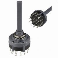
SWITCH ROTARY 4P 3POS EYELET
Manufacturer
C&K Components
Series
Ar
Datasheet
1.767B00201.pdf
(5 pages)
Specifications of A40315RNZQ
Number Of Positions
3
Number Of Decks
1
Number Of Poles Per Deck
4
Circuit Per Deck
4P3T
Contact Rating @ Voltage
2.5A @ 125VAC
Actuator Type
Flatted (6.35mm dia)
Mounting Type
Panel Mount
Termination Style
Solder Lug
Orientation
Vertical
Angle Of Throw
30°
No. Of Poles
4
No. Of Switch Positions
3
Contact Current Ac Max
2.5A
Contact Current Dc Max
350mA
Contact Voltage Ac Max
125V
Contact Voltage Dc Max
125V
Circuitry
4P3T
Total # Of Positions
3
Pole Throw Configuration
4P
Switch Configuration
N.C.
Actuator Style
Shaft
Actuator Material
Glass/Nylon 6/6
Current Rating (max)
2.5A
Illumination Type
Not Required
Ac Voltage Rating (max)
125VVAC
Dc Voltage Rating (max)
125VVDC
Contact Material
Coin Silver
Contact Plating
Silver
Product Height (mm)
66.94mm
Product Depth (mm)
26.19mm
Product Length (mm)
26.19mm
Operating Temp Range
-30C to 85C
Mounting Style
Panel
Terminal Type
Solder Lug
Index Angle
30 deg
Contact Style
Non Shorting
Contact Form
3PST
Color
Black
Dielectric Strength
1000 V
Voltage Rating
125 Volts
Current Rating
2.5 A
Actuator
Flatted 1.5 in High
Contact Rating
2.5 Amps at 125 Volts
Voltage Rating Ac
125 Volts
Voltage Rating Dc
125 Volts
Lead Free Status / RoHS Status
Lead free / RoHS Compliant
Lead Free Status / RoHS Status
Compliant, Lead free / RoHS Compliant
Other names
*A40315RNZQ
CKC7008
CKC7008
Available stocks
Company
Part Number
Manufacturer
Quantity
Price
Company:

Part Number:
A40315RNZQ
Manufacturer:
CK
Quantity:
100


Setting Stops on A112 and A125 Models
The number of switch positions is adjustable on A112
and A125 models only by means of a stop ring provided
with each switch. The number of positions is pre-set on
all other models and the stop ring is factory installed.
Soldering, Cleaning and Assembly Instructions for ‘MC’ Termination Option
Soldering
1. Insert switch base only into PC board.
2. Do not bend terminals.
3. Wave soldering recommended at
4. Hand solder at 500F, 10 sec.
Switch Assembly
1. Hold housing/shaft assembly by housing. Remove
2. Do not push on switch shaft. Detent mechanism will
3. While holding switch housing, align locating tab on
4. Push firmly on housing until latches snap in place.
5. Remove clip from shaft and discard. Assembly is
Stop ring
PART NO.
767B00201
Material: Brass
Finish: Nickel plated
NONE
500F solder temperature.
max./terminal.
protective cap by squeezing tabs and discard. (FIG. 1)
come apart.
base with notch on housing and engage 4 housing
latches in slots on base. (FIG. 2)
complete. (FIG. 3)
NO SEAL
E
EPOXY SEAL
FUNCTION
AVAILABLE HARDWARE
F
SPLASHPROOF BUSHING SEAL
K–7
Cleaning
1. Flux clean using vapor degreaser and forced
2. Do not allow switch base to ‘trap’ fluids.
3. Freon TMC, TF or Methylene Chloride give
To set stops: Turn shaft fully counter-clockwise and
insert stop ring tab in desired hole. Install lockwasher
and nut to retain stop ring for both PC and panel
mounting. Switch without stop ring has 12 positions.
rinse or triple bath method.
excellent results.
SPLASHPROOF
BUSHING SEAL
(FIG. 1)
1-4 Pole Rotary Switches
REMOVABLE CLIP
K
EPOXY & SPLASHPROOF BUSHING SEAL
Specifications and dimensions subject to change
(FIG. 2)
www.ck-components.com
LOCATING
Dimensions are shown: mm
STANDOFF
A Series
TAB
(FIG. 3)
K
Related parts for A40315RNZQ
Image
Part Number
Description
Manufacturer
Datasheet
Request
R

Part Number:
Description:
Rotary Switches 4P 3 POS ROTARY SW
Manufacturer:
C&K Components
Part Number:
Description:
ANALOG ROCKER C&K DELTATECH
Manufacturer:
C&K Components
Part Number:
Description:
QUARDANT MODUL C&K DELTATECH
Manufacturer:
C&K Components
Datasheet:
Part Number:
Description:
TOGGLE,THT-PC,SPDT,ON-OFF-ON,ACT-DXL:6.09X17.15MM,BUSH-THREADED,AU
Manufacturer:
C&K Components
Part Number:
Description:
SMARTCARD CONNECTOR *Y1112-2013AP LFT
Manufacturer:
C&K Components
Part Number:
Description:
Connector reel; SIM card; 6 contacts; hinged; no switch lock
Manufacturer:
C&K Components
Part Number:
Description:
CCM03-MKII SmartCard Conn for SIM/SAM cards, 6-contacts hinged 1k reel
Manufacturer:
C&K Components