DLB2141W01-L1C NKK Switches, DLB2141W01-L1C Datasheet - Page 4
DLB2141W01-L1C
Manufacturer Part Number
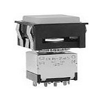
DLB2141W01-L1C
Description
SW PB ILLUM DPDT MOM SQ RED SLD
Manufacturer
NKK Switches
Series
DLBr
Type
Illuminatedr
Specifications of DLB2141W01-L1C
Circuit
DPDT
Switch Function
On-Mom
Contact Rating @ Voltage
5A @ 125VAC
Actuator Type
Square Button
Illumination Type, Color
Incandescent, Red
Illumination Voltage (nominal)
28 VAC
Mounting Type
Panel Mount
Termination Style
Solder Lug
Pole Throw Configuration
DPDT
Switch Configuration
ON ON
Actuator Style
Square Button
Actuator Material
Polyacetal Resin
Current Rating (max)
5A
Illumination Type
Incandescent Lamp
Ac Voltage Rating (max)
250VVAC
Dc Voltage Rating (max)
30VVDC
Contact Material
Silver
Contact Plating
Silver
Mechanical Life
30000
Product Height (mm)
51.6mm
Product Depth (mm)
23.8mm
Operating Temp Range
-10C to 50C
Mounting Style
Panel
Terminal Type
Solder Lug
Lead Free Status / RoHS Status
Contains lead / RoHS non-compliant


NKK Switches • email: sales@nkkswitches.com • Phone (480) 991- 0942 • Fax (480) 998-1435 • www.nkkswitches.com
AT604 & AT604N
T-1
Pole
W
DP
01
A
0
3
3
3 4
⁄
⁄
⁄
⁄ Midget Groove Base
4
Note: This dual rated option is suitable when two or more identical switches are used in logic and in power circuits within
Gold over Silver
Silver
No Lamp
Solder Lug
(2.0)
.079
DLB2141
DLB2145
.043
the same application. See Supplement Index for complete explanation of dual rating and operating range.
(1.1)
Model
Thk = (0.7)
.028
(2.5)
.098
(4.5)
.177
INCANDESCENT & NEON LAMP CODES & SPECIFICATIONS
Normal
Voltage
Current
Endurance
Ambient Temperature Range
Plunger Position
( ) = Momentary
ON
ON
AT604 Incandescent 6-, 14-, or
28-volt; AT604N Neon 110-volt
Code 0 indicates that no lamp is used with the solid or design caps.
Electrical specifi cations are determined at a basic temperature of 25°C.
Wiring for Solder Lug Terminals
Power terminal hole of .035” x .079”
(0.9mm x 2.0mm) accommodates
one solid 20-gauge wire or two solid
or stranded 22-gauge wires.
Lamp terminal hole of .035” (0.9mm)
diameter accommodates one solid
20-gauge wire.
Incandescent & Neon lamps can be used with solid & design caps.
Down
(ON)
ON
Average Hours
CONTACT MATERIALS & RATINGS
Lamp circuit is independent of switch operation.
Power Level
Power Level
or Logic Level
Connected Terminals
2-3 5-6
Normal
POLES & CIRCUITS
V
I
TERMINALS
200mA
1,000
6V AC
Power Rated Pushbuttons
E
2-1 5-4
Down
14V AC
80mA
750
–20°C ~ +50°C
G
5A @ 125V AC
or 0.4VA maximum @ 28V AC/DC maximum
3A @ 125V AC & 250V AC
DPDT
Notes: Terminal numbers are not actually on the
03
Throw & Power/Lamp Schematics
28V AC
40mA
1,000
switch. Lamp circuit is isolated and
requires an external power source.
3
Straight PC
(1.17)
.046
L
Thk = (0.7)
.028
2
(4.8)
.189
(COM)
1
.252
(6.4)
110V AC
10,000
1.5mA
*
6
N
5
Series DLB
4
2
3
1
*
Resistors: 33K
ohms for 110V
AC; 100K ohms
for 220V AC
Recommended
L2
L1
L (+)
.073
(1.8) Dia Typ
4
6
5
(3.85) Typ
.152
(4.3) Typ
.169
(2.9) Typ
.115
(14.4)
.567
(-) L
3-05
Related parts for DLB2141W01-L1C
Image
Part Number
Description
Manufacturer
Datasheet
Request
R

Part Number:
Description:
Rocker Switches & Paddle Switches High In-rush Rated Rocker Switch
Manufacturer:
NKK Switches
Datasheet:
Part Number:
Description:
Rocker Switches & Paddle Switches High In-rush Rated Rocker Switch
Manufacturer:
NKK Switches
Datasheet:
Part Number:
Description:
Rocker Switches & Paddle Switches High In-rush Rated Rocker Switch
Manufacturer:
NKK Switches
Datasheet:
Part Number:
Description:
Rocker Switches & Paddle Switches High In-rush Rated Rocker Switch
Manufacturer:
NKK Switches
Datasheet:

Part Number:
Description:
Pushbutton Switches SPST ON(OFF) 15/32'
Manufacturer:
NKK Switches
Datasheet:

Part Number:
Description:
Pushbutton Switches SPST OFF(ON) 15/32'
Manufacturer:
NKK Switches
Datasheet:

Part Number:
Description:
Pushbutton Switches ON(OFF) NORM CLSD 3A RED PLNGR LUG 15/32
Manufacturer:
NKK Switches
Datasheet:

Part Number:
Description:
Pushbutton Switches SPDT ON-(ON)
Manufacturer:
NKK Switches
Datasheet:

Part Number:
Description:
Pushbutton Switches ON-(ON) RND BUSH MNT RED LED RED/RED CAP
Manufacturer:
NKK Switches
Datasheet:
Part Number:
Description:
Pushbutton Switches SPST ON-(OFF) STRT
Manufacturer:
NKK Switches
Datasheet:
Part Number:
Description:
Pushbutton Switches OFF(ON) NORM OPEN 3A RED CAP LUG 15/32
Manufacturer:
NKK Switches
Datasheet:
Part Number:
Description:
Pushbutton Switches ILLUM PUSHBUTTON SPDT
Manufacturer:
NKK Switches
Datasheet:
Part Number:
Description:
Pushbutton Switches OFF(ON) NORM OPEN 3A BLK CAP LUG 15/32
Manufacturer:
NKK Switches
Datasheet:
Part Number:
Description:
Pushbutton Switches SPST NO Metric Thrd Blk Plunge w/Blu Cap
Manufacturer:
NKK Switches
Datasheet:
Part Number:
Description:
Pushbutton Switches SPST OFF-(ON) NO 3A
Manufacturer:
NKK Switches
Datasheet: