KB16CKW01-12-GB NKK Switches, KB16CKW01-12-GB Datasheet - Page 4
KB16CKW01-12-GB
Manufacturer Part Number
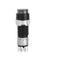
KB16CKW01-12-GB
Description
SW PB ILLUM SPDT ALT RND BL SLD
Manufacturer
NKK Switches
Series
KBr
Type
Illuminatedr
Datasheet
1.AT701.pdf
(13 pages)
Specifications of KB16CKW01-12-GB
Circuit
SPDT
Switch Function
On-On
Contact Rating @ Voltage
1A @ 125VAC
Actuator Type
Round Button
Illumination Type, Color
Incandescent, Blue
Illumination Voltage (nominal)
12 VAC
Mounting Type
Panel Mount
Termination Style
Solder Lug
Pole Throw Configuration
SPDT
Switch Configuration
ON ON
Actuator Style
Round Button
Current Rating (max)
1A
Illumination Type
Incandescent Lamp
Ac Voltage Rating (max)
250VVAC
Dc Voltage Rating (max)
30VVDC
Contact Material
Silver
Contact Plating
Gold
Housing Material
Polyamide/Polyamide
Mechanical Life
100000
Product Height (mm)
38.5mm
Product Depth (mm)
14mm
Product Length (mm)
14mm
Operating Temp Range
-25C to 50C
Mounting Style
Panel
Terminal Type
Solder Lug
Lead Free Status / RoHS Status
Lead free / RoHS Compliant
Other names
KB16CKW01-12-GB-RO
KB16CKW01-12-GB-RO
KB16CKW01-12-GB-RO


D
Series KB
D26
Pole
DP
SP
S
K
K
Keyway
Without
Housing available in black only. Bezel or barrier is an integral part of the switch body.
.551” (14.0mm)
Square
.551” (14.0mm)
Square
No barrier
No barrier
* KB16
* KB26
Model
KB15
KB25
Panel thicknesses, when using optional accessories, are shown with the accessories at the end of this KB section.
* When in latchdown position for the alternate circuit, cap position is .055” (1.4mm) above the built-in bezel.
Bezel or barrier is an integral part of the switch body. One mounting nut AT057 supplied with each switch.
Normal
( ) = Momentary
Plunger Position
ON
ON
ON
ON
(12.3) Dia
.484
With barrier
With barrier
Bushing Mounting
Panel Thickness:
(0.5 ~ 8.0mm)
.020” ~ .315”
Down
(ON)
(ON)
ON
ON
Bezel or barrier is an integral part of the switch body.
MOUNTING TYPES & SHAPES
2-3 5-6
Normal
Connected Terminals
M
C
2-3
POLES & CIRCUITS
www.nkk.com
.551” (14.0mm)
Round
.551” (14.0mm)
Round
Bushing Mounting
Snap-in Mounting
HOUSING
Panel Cutouts
2-1 5-4
Down
(12.3) Dia
.484
2-1
(4.9)
.193
With
Keyway
Notes:
SPDT
DPDT
3
Throw & Switch/Lamp Schematics
Switch is marked with “+” and “–”.
Lamp circuit is isolated and requires
external power source.
3
N
R
2
Panel Thickness:
(1.0 ~ 3.5mm)
.039” ~ .138”
(COM)
1
Miniature Pushbuttons
.551” x .728” (14.0mm x 18.5mm)
Rectangular
.551” x .728” (14.0mm x 18.5mm)
Rectangular
2 (COM)
6
No barrier
No barrier
1
5
Snap-in Mounting
4
.047
(1.2) R
L (+)
L (+)
.268
(6.8)
With barrier
With barrier
(12.3) Dia
.484
(-) L
(-) L
Related parts for KB16CKW01-12-GB
Image
Part Number
Description
Manufacturer
Datasheet
Request
R

Part Number:
Description:
SWITCH PB ILLUM SPDT ALT ACT
Manufacturer:
NKK Switches
Datasheet:
Part Number:
Description:
SW PB ILLUM SPDT ALT RND GN SLD
Manufacturer:
NKK Switches
Datasheet:
Part Number:
Description:
SW PB ILLUM SPDT ALT RND RD SLD
Manufacturer:
NKK Switches
Datasheet:
Part Number:
Description:
SW PB ILLUM SPDT ALT RND YW SLD
Manufacturer:
NKK Switches
Datasheet:
Part Number:
Description:
SW PB ILLUM SPDT ALT RND WH SLD
Manufacturer:
NKK Switches
Datasheet:
Part Number:
Description:
SW PB ILLUM SPDT ALT RND RD SLD
Manufacturer:
NKK Switches
Datasheet:
Part Number:
Description:
SWITCH ILLUM PB SPDT RND GREEN
Manufacturer:
NKK Switches
Datasheet:

Part Number:
Description:
SW ILLUM PB SPDT RND NEON CLEAR
Manufacturer:
NKK Switches
Datasheet:
Part Number:
Description:
SW PB ILLUM SPDT ALT RND GN SLD
Manufacturer:
NKK Switches
Datasheet:
Part Number:
Description:
SW PB ILLUM SPDT ALT RND AMB SLD
Manufacturer:
NKK Switches
Datasheet:
Part Number:
Description:
SW PB ILLUM SPDT ALT RND RD SLD
Manufacturer:
NKK Switches
Datasheet:
Part Number:
Description:
SW PB ILLUM SPDT ALT RND GN SLD
Manufacturer:
NKK Switches
Datasheet:

Part Number:
Description:
Pushbutton Switches SPDT ON-ON RND AMB
Manufacturer:
NKK Switches
Datasheet:
Part Number:
Description:
Pushbutton Switches SPDT ON-ON RND GRN
Manufacturer:
NKK Switches
Part Number:
Description:
Pushbutton Switches SPDT ON-ON 1A RND ILLUM SUPER WHITE
Manufacturer:
NKK Switches
Datasheet: