A165L-AWM-24D-2 Omron, A165L-AWM-24D-2 Datasheet - Page 22
A165L-AWM-24D-2
Manufacturer Part Number
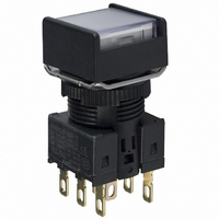
A165L-AWM-24D-2
Description
SWITCH PB SQ MOM DPDT ILLUM WHT
Manufacturer
Omron
Series
A16r
Type
Illuminatedr
Datasheet
1.A16-5DSG.pdf
(28 pages)
Specifications of A165L-AWM-24D-2
Circuit
DPDT
Switch Function
On-Mom
Contact Rating @ Voltage
5A @ 125VAC
Actuator Type
Square Button
Illumination Type, Color
LED, White
Illumination Voltage (nominal)
24 VDC
Mounting Type
Panel Mount
Termination Style
Solder, Quick Connect - .110" (2.8mm)
Contact Form
DPDT
Contact Rating
5 Amps at 125 Volts
Actuator
Square
Mounting Style
Snap In
Illumination
Illuminated
Illumination Color
White LED
Body Shape
Square
Dielectric Strength
2000 Volts
Features
Terminal layout simplifies common wiring
Insulation Resistance
100 MOhms
Mounting Angle
Straight
Operating Force
4.91 N
Water / Moisture Rating
IP65
Ip Rating
IP65
Lead Free Status / RoHS Status
Lead free / RoHS Compliant
Lead Free Status / RoHS Status
Lead free / RoHS Compliant, Lead free / RoHS Compliant
Other names
A165LAWM24D2
Z1302
Z1302


Dimensions
PCB Terminals (Lamp terminals are also present on non-lighted models.)
Terminal Arrangement
Voltage-reduction Lighting (Lamp terminals are also present on non-lighted models.)
Solder Terminals
• The voltage-reduction circuit is built in.
Note: Secure the panel to the board using stud bolts
A = 24 min.: Rectangular
A = 21 min.: Square or round
L = 24 min.
Use a PCB with a thickness of 1.6 mm.
(Bottom View)
PCB Cutouts
Dimensions of
PCB Terminals
2.7
if force will be applied to the board after wiring.
Lamp terminal (t=0.5)
0.8
1.5
DPDT lighted models
(Bottom view)
3.5
20 ± 0.1 4.85 ± 0.05
5.3
12.4 ± 0.05
Side with TOP indicated
Side with direction arrow
Five, 1 dia.
Model, rating, and lot
number indication
Lighted SPDT Switches
6.3 ± 0.05
NC
NO
C
L
L
4.85
12.4
18.6
NC
NO
C
Two, 5 dia.
Side with TOP indicated
A ± 0.1
Terminal Arrangement
(Bottom View)
Screw-Less Clamps
Red (Release button)
White (Release button)
Black (Release button)
Black (Release button)
• Voltage-reduction lighting models with Screw-Less Clamps (A16L-@T1-2S, A16L-@T2-2S)
incorporate voltage-reduction circuits.
COM
SW 1
NC
NO
L-
L ± 0.1
A = 24 min.: Rectangular
A = 21 min.: Square or round
L = 24 min.
Use a PCB with a thickness of 1.6 mm.
Note: Secure the panel to the board using stud bolts
Dimensions of
PCB Terminals
(Bottom View)
PCB Cutouts
Lamp terminal (t=0.5)
2.7
if force will be applied to the board after wiring.
0.8
1.5
3.5
20 ± 0.1
5.3
DPDT lighted models
Red (Release button)
12.4 ± 0.05
Black (Release button)
Side with TOP indicated
4.85 ± 0.05
Lighted DPDT Switches
12-3.1 dia. (Insertion hole)
Red (Release button)
White (Release button)
Black (Release button)
Black (Release button)
6.3 ± 0.05
4.85
12.4
18.6
Two, 5 dia.
Terminal Arrangement
Side with TOP indicated
(Bottom View)
6.3 ± 0.05
A ± 0.1
SW 1
COM
Side indicating TOP
NC
NO
NC2
NO2
C2
C2
L-
SW 2
COM
NC
NO
(Unit: mm)
-
+
+
A16
NC1
NO1
C1
C1
L ± 0.1
Eight, 1 d
22
Related parts for A165L-AWM-24D-2
Image
Part Number
Description
Manufacturer
Datasheet
Request
R

Part Number:
Description:
SWITCH PB SQ MOM DPDT WHITE
Manufacturer:
Omron
Datasheet:
Part Number:
Description:
SWITCH PB ILLUM SQR MOM SPDT WHT
Manufacturer:
Omron
Datasheet:
Part Number:
Description:
SWITCH PB ILLUM SQR MOM SPDT WHT
Manufacturer:
Omron
Datasheet:
Part Number:
Description:
SWITCH PB ILLUM SQR MOM SPDT WHT
Manufacturer:
Omron
Datasheet:
Part Number:
Description:
SWITCH PB ILLUM SQR MOM DPDT WHT
Manufacturer:
Omron
Datasheet:
Part Number:
Description:
SWITCH PB ILLUM SQR MOM DPDT WHT
Manufacturer:
Omron
Datasheet:
Part Number:
Description:
SWITCH PB ILLUM SQR MOM DPDT WHT
Manufacturer:
Omron
Datasheet:
Part Number:
Description:
SWITCH PB ILLUM SQR MOM SPDT WHT
Manufacturer:
Omron
Datasheet:

Part Number:
Description:
SWITCH PB ILLUM SQR MOM SPDT WHT
Manufacturer:
Omron
Datasheet:
Part Number:
Description:
SWITCH PB ILLUM SQR MOM SPDT WHT
Manufacturer:
Omron
Datasheet:
Part Number:
Description:
SWITCH PB ILLUM SQR MOM DPDT WHT
Manufacturer:
Omron
Datasheet:
Part Number:
Description:
SWITCH PB ILLUM SQR MOM DPDT WHT
Manufacturer:
Omron
Datasheet:

Part Number:
Description:
CAP 16 SERIES SQUARE WHITE
Manufacturer:
Omron
Datasheet: