A165L-JWM-24D-2 Omron, A165L-JWM-24D-2 Datasheet - Page 21
A165L-JWM-24D-2
Manufacturer Part Number
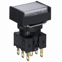
A165L-JWM-24D-2
Description
SWITCH PB RECT MOM DPDT ILLUM
Manufacturer
Omron
Series
A16r
Type
Illuminatedr
Specifications of A165L-JWM-24D-2
Circuit
DPDT
Switch Function
On-Mom
Contact Rating @ Voltage
5A @ 125VAC
Actuator Type
Rectangular Button
Illumination Type, Color
LED, White
Illumination Voltage (nominal)
24 VDC
Mounting Type
Panel Mount
Termination Style
Solder, Quick Connect - .110" (2.8mm)
Contact Form
DPDT
Contact Rating
10 mAmps
Actuator
Rectangular
Supply Voltage
24 Volts
Mounting Style
Snap In
Terminal Seal
IP65
Illumination
Illuminated
Illumination Color
White
Features
Terminal layout simplifies common wiring
Mounting Angle
Horizontal
Operating Force
4.91 N
Lead Free Status / RoHS Status
Lead free / RoHS Compliant
Lead Free Status / RoHS Status
Lead free / RoHS Compliant, Lead free / RoHS Compliant
Other names
A165LJWM24D2
Z1306
Z1306


Dimensions
Panel Cutouts
Solder Terminals and Screw-less Clamp Connectors
Terminal Arrangement
Models without Reduced-voltage Lighting
Solder Terminals
Note:• Make sure the thickness of the mounting panel is between 0.5 and 3.2
Rectangular A16@-@J/M16@-@J
Dimensions of
Terminal Holes
16
• If the panel is to be finished with coating, etc., make sure that the panel
• Figures in parentheses are for Screw-less Clamp Connectors.
+0.2
1.5
2.8
0
mm. If, however, a Switch Guard or Dust Cover is used, the thickness
of the mounting panel must be between 0.5 and 2 mm.
meets the specified dimensions after coating.
dia.
(Top View)
(25 min.)
24 min.
2.6
0.9
Lamp terminal
7.4
Lighted SPDT Switches
(33 min.)
19 min.
12.2
18
Note: The L+ is not shown on the Switch.
Square A16@-A/M16@-A
Round A16@-T/M16@-T
16
+0.2
0
Terminal Arrangement
dia.
(Top View)
(Bottom View)
(25 min.)
19 min.
(Non-lighted Pushbutton Switches are also provided with lamp terminals.)
(33 min.)
COM
SW1
19 min.
NC
NO
L-
PCB Terminals
1.5
2.8
Note:• Ensure that the variation in the distance between the centers of
Dimensions of
Terminal Holes
Rectangular A16@-J/M16@-J
9.1 ± 0.05
14.7 ± 0.05 dia.
Lamp terminal
• Make sure the thickness of the mounting panel is between 0.5 and 3.2
• If the panel is to be finished with coating, etc., make sure that the panel
neighboring mounting holes is less than ±0.1 mm.
mm. If, however, a Switch Guard or Dust Cover is used, the thickness
of the mounting panel must be between 0.5 and 2 mm.
meets the specified dimensions after coating.
2.6
0.9
16
+0.2
0
5.1 ± 0.05
dia.
(Top View)
7.4
24 min.
Lighted DPDT Switches
12.2
18
Note: The L+ is not shown on the Switch.
24 min.
Terminal Arrangement
Square A16@-A/M16@-A
Round A16@-T/M16@-T
(Bottom View)
16
+0.2
0
dia.
(Top View)
(25 min.)
19 min.
COM
SW1
NC
NO
L-
COM
SW2
NC
NO
(Unit: mm)
(33 min.)
19 min.
A16
21
Related parts for A165L-JWM-24D-2
Image
Part Number
Description
Manufacturer
Datasheet
Request
R

Part Number:
Description:
SWITCH PB RECT MOM DPDT WHITE
Manufacturer:
Omron
Datasheet:
Part Number:
Description:
SWITCH PB ILLUM RCT MOM SPDT WHT
Manufacturer:
Omron
Datasheet:
Part Number:
Description:
SWITCH PB ILLUM RCT MOM SPDT WHT
Manufacturer:
Omron
Datasheet:
Part Number:
Description:
SWITCH PB ILLUM RCT MOM SPDT WHT
Manufacturer:
Omron
Datasheet:
Part Number:
Description:
SWITCH PB ILLUM RCT MOM DPDT WHT
Manufacturer:
Omron
Datasheet:
Part Number:
Description:
SWITCH PB ILLUM RCT MOM DPDT WHT
Manufacturer:
Omron
Datasheet:
Part Number:
Description:
SWITCH PB ILLUM RCT MOM DPDT WHT
Manufacturer:
Omron
Datasheet:
Part Number:
Description:
SWITCH PB ILLUM RCT MOM SPDT WHT
Manufacturer:
Omron
Datasheet:
Part Number:
Description:
SWITCH PB ILLUM RCT MOM SPDT WHT
Manufacturer:
Omron
Datasheet:
Part Number:
Description:
SWITCH PB ILLUM RCT MOM SPDT WHT
Manufacturer:
Omron
Datasheet:
Part Number:
Description:
SWITCH PB ILLUM RCT MOM DPDT WHT
Manufacturer:
Omron
Datasheet:
Part Number:
Description:
SWITCH PB ILLUM RCT MOM DPDT WHT
Manufacturer:
Omron
Datasheet:

Part Number:
Description:
CAP 16 SERIES RECTANGULAR WHITE
Manufacturer:
Omron
Datasheet: