JB15LPE-JE NKK Switches, JB15LPE-JE Datasheet - Page 2
JB15LPE-JE
Manufacturer Part Number
JB15LPE-JE
Description
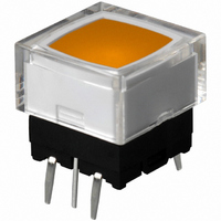
SWITCH TACT ILLUM SPST 180GF YEL
Manufacturer
NKK Switches
Series
JBr
Type
Illuminatedr
Datasheet
1.AT4076BF.pdf
(6 pages)
Specifications of JB15LPE-JE
Circuit
SPST-NO
Switch Function
Off-Mom
Contact Rating @ Voltage
0.05A @ 24VDC
Actuator Type
Square Button
Illumination Type, Color
LED, Yellow
Mounting Type
Through Hole
Termination Style
PC Pin
Operating Force
180 gf
Actuator
Short
Contact Current Rating
50 mAmps at 24 Volts
Ground Terminal
No
Contact Form
SPST
Body Size
12 mm L x 12 mm W x 4.2 mm H
Mounting Style
Vertical
Contact Rating
50 mAmps at 24 Volts
Pole Throw Configuration
SPST
Switch Function Configuration
N.O.
Actuator Style
Button
Actuator Color
Clear/Yellow
Actuator Length (mm)
7mm
Current Rating (max)
0.05A
Illumination Type
Led
Voltage Rating (vdc)
24V
Mechanical Life
5000000
Contact Material
Beryllium Copper
Contact Plating
Silver
Base/housing Material
(Glass Fiber/Polybutylene Terephthalate)/N/A
Product Length (mm)
12.3mm
Product Depth (mm)
12.3mm
Product Height (mm)
11.2mm
Operating Temp Range
-25C to 70C
Body Orientation
Straight
Terminal Type
PC Pins
Lead Free Status / RoHS Status
Lead free / RoHS Compliant
Illumination Voltage (nominal)
-
Lead Free Status / Rohs Status
Lead free / RoHS Compliant
Other names
360-1263


Distinctive
Choice of dimensions from PCB to top of cap adds to design flexibility.
Bright, full-face illumination with red, green, or yellow LEDs
for attractive, functional panel layouts.
Higher operating force type provides more pronounced
operating feel.
Dome contact gives crisp tactile feedback to positively
indicate circuit transfer and assures high reliability
and long life of up to 5,000,000 operations.
Rubber seal construction prevents contact contamination
and allows automated soldering and cleaning.
Slanted terminals provide a spring type action which ensures
secure mounting and prevents dislodging during wave soldering.
Molded-in terminals are part of the sealed construction which allows
automated soldering and cleaning.
Terminal spacing conforms to standard .100” (2.54mm) PCB grid.
Illuminated Low Profile Process Sealed Tactiles
4
3
1
These single pole, single throw switches can be used in a key-
board matrix and, using strapped terminals, achieve a com-
mon bus electrical configuration on a single-sided PC board.
4
1
7
A
5
2
2
5
8
0
9
7
Common Bus Matrix
3
9
B
6
13
10
12
11
6
8
Characteristics
3
4
5
6
8
9
0
A
B
1
2
7
1 2 3 4 5 6 7 8 9 10 11 12 13
P C T e r m i n a t i o n s
Red = PCB Trace
= ON
Black = Switch Circuit
www.nkk.com
5
These single pole, single throw switches can be
arranged on a single-sided PC board matrix
with strapped terminals to achieve an X-Y type
electrical interconnection.
1
4
7
A
4
2
5
8
0
3
X-Y Matrix
B
3
6
9
2
6
7
1
Series JB
PC Ter m i na t i ons
2
3
4
5
6
7
8
9
0
A
B
1
Actual Size
1 2 3 4 5 6 7
= ON
J29
J
Related parts for JB15LPE-JE
Image
Part Number
Description
Manufacturer
Datasheet
Request
R

Part Number:
Description:
Tactile & Jog Switches OFF-(ON) PC MOUNT SPECIAL YELLOW LED
Manufacturer:
NKK Switches
Datasheet:

Part Number:
Description:
SWITCH TACT ILLUM SPST 180GF YEL
Manufacturer:
NKK Switches
Datasheet:

Part Number:
Description:
SW TACT SPST ILL YELLOW STR PCB
Manufacturer:
NKK Switches
Datasheet:

Part Number:
Description:
SW TACT ILLUM SPST STR YELLOW
Manufacturer:
NKK Switches
Datasheet:
Part Number:
Description:
SW TACT SPST ILL YLW YLW CAP PCB
Manufacturer:
NKK Switches
Datasheet:
Part Number:
Description:
SW TACT ILLUM SPST STR YELLOW
Manufacturer:
NKK Switches
Datasheet:
Part Number:
Description:
SW TACT ILLUM SPST STR YELLOW
Manufacturer:
NKK Switches
Datasheet:
Part Number:
Description:
SWITCH TACT EXTENDED PC MNT WHT
Manufacturer:
NKK Switches
Datasheet:

Part Number:
Description:
Rocker Switches & Paddle Switches High In-rush Rated Rocker Switch
Manufacturer:
NKK Switches
Datasheet:
Part Number:
Description:
Rocker Switches & Paddle Switches High In-rush Rated Rocker Switch
Manufacturer:
NKK Switches
Datasheet:
Part Number:
Description:
Rocker Switches & Paddle Switches High In-rush Rated Rocker Switch
Manufacturer:
NKK Switches
Datasheet:
Part Number:
Description:
Rocker Switches & Paddle Switches High In-rush Rated Rocker Switch
Manufacturer:
NKK Switches
Datasheet:

Part Number:
Description:
Pushbutton Switches SPST ON(OFF) 15/32'
Manufacturer:
NKK Switches
Datasheet:

Part Number:
Description:
Pushbutton Switches SPST OFF(ON) 15/32'
Manufacturer:
NKK Switches
Datasheet:

Part Number:
Description:
Pushbutton Switches ON(OFF) NORM CLSD 3A RED PLNGR LUG 15/32
Manufacturer:
NKK Switches
Datasheet: