H1011U2F805NQ C&K Components, H1011U2F805NQ Datasheet - Page 4
H1011U2F805NQ
Manufacturer Part Number
H1011U2F805NQ
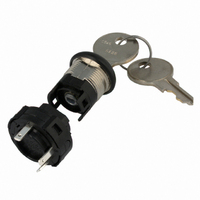
Description
SWITCH KEYLOCK SPDT SP.110 QC5PC
Manufacturer
C&K Components
Series
Hr
Type
Tumbler Switchr
Datasheet
1.115140126.pdf
(5 pages)
Specifications of H1011U2F805NQ
Angle Of Throw
90°
Circuit
SPDT
Number Of Positions
2
Contact Rating @ Voltage
12A @ 125VAC
Actuator Type
Flat Key
Mounting Type
Panel Mount
Termination Style
Quick Connect - .110" (2.8mm)
Key Removable Positions
1 and 2
Pole Throw Configuration
SP
Current Rating (max)
12A
Terminal Type
Quick Connect
Mounting Style
Panel
Key Style
Flat Key
Key Material
Brass
Operating Temp Range
-30C to 85C
Ac Voltage Rating (max)
250VVAC
Dc Voltage Rating (max)
125VVDC
Contact Plating
Silver
Contact Material
Copper
Product Length (mm)
22.35mm
Product Depth (mm)
22.35mm
Product Height (mm)
42.21mm
Contact Form
SPDT
Indexing
90 deg
Contact Rating
12 Amps
Housing Material
Nylon
Lead Free Status / RoHS Status
Lead free / RoHS Compliant
Lead Free Status / RoHS Status
Compliant, Lead free / RoHS Compliant
Other names
*H1011U2F805NQ
CKN10112
H1011U2F805NQ
Q1544285
CKN10112
H1011U2F805NQ
Q1544285


L
H Series
4 & 6 Tumbler Power Switchlocks
1
2
Nut part number: 175050700
N
CONTACTS & TERMINALS: Copper, with gold plate over nickel plate.
CONTACTS & TERMINALS: Copper, silver plated.
OPTION
CODE
Q
B
WITH NUT
COMPLIANT *
RoHS
YES
YES
COMPATIBLE *
0.468 +.062
RoHS
MOUNTING/LOCK STYLE
YES
YES
-.000
CONTACT MATERIAL
0.225
± 0.010
Clip part number: 906B00000
D
TERMINAL MATERIAL
CONTACT AND
WITH CLIP
0.034
90
0.100
SILVER
GOLD
0
0.062
Switch and Lock Assembly Instructions
0.062
0.688
1
2
0.965
± 0.010
R 0.688
0.085
* Note: See Technical Data section of this catalog for RoHS compliant and compatible
definition and specifications.
All models
1. Place lock assembly in mounting hole on panel,
2. Align keying tab on switch assembly with keying slot
3. Snap assemblies together.
4. Switch installation is permanent. Switch cannot be
LOW LEVEL/DRY CIRCUIT
0.563
0.327
0.500
secure with mounting nut.
on lock assembly.
removed from lock after assembly. Attempting to separate
switch and lock may cause damage to switchlock.
L–42
± .003
R 0.048
POWER
0.235
1.000
o
± .010
with all options when ordered with ‘Q’ contact material.
0.470
Ø 0.136
R 0.030 ± .010
0.657
0.652
BURR SIDE UP
GRAIN
DIRECTION
R 0.375
12 AMPS @ 125 V AC; 6 AMPS @ 250 V AC;
1 AMP @ 125 V DC (UL/CSA).
0.105
0.4 VA MAX. @ 20 V AC or DC MAX.
± .010
RATING
Specifications and dimensions subject to change
MOUNTING
STYLES
D
N
www.ck-components.com
PANEL MOUNTING
Dimensions are shown: Inch (mm)
.065-.085 (1,65-2,16)
PANEL THICKNESS
.195 (4,95) max.
Related parts for H1011U2F805NQ
Image
Part Number
Description
Manufacturer
Datasheet
Request
R

Part Number:
Description:
Rotary Switches 4P 3 POS ROTARY SW
Manufacturer:
C&K Components
Part Number:
Description:
ANALOG ROCKER C&K DELTATECH
Manufacturer:
C&K Components
Part Number:
Description:
QUARDANT MODUL C&K DELTATECH
Manufacturer:
C&K Components
Datasheet:
Part Number:
Description:
TOGGLE,THT-PC,SPDT,ON-OFF-ON,ACT-DXL:6.09X17.15MM,BUSH-THREADED,AU
Manufacturer:
C&K Components
Part Number:
Description:
SMARTCARD CONNECTOR *Y1112-2013AP LFT
Manufacturer:
C&K Components
Part Number:
Description:
Connector reel; SIM card; 6 contacts; hinged; no switch lock
Manufacturer:
C&K Components
Part Number:
Description:
CCM03-MKII SmartCard Conn for SIM/SAM cards, 6-contacts hinged 1k reel
Manufacturer:
C&K Components