97R02ST Grayhill Inc, 97R02ST Datasheet - Page 4
97R02ST
Manufacturer Part Number
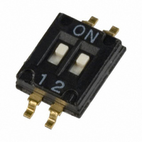
97R02ST
Description
SWITCH DIP HALF PITCH 2POS SMD
Manufacturer
Grayhill Inc
Series
97r
Specifications of 97R02ST
Circuit
SPST
Number Of Positions
2
Contact Rating @ Voltage
0.025A @ 24VDC
Actuator Type
Standard
Actuator Level
Flush
Mounting Type
Surface Mount
Orientation
Top Actuated
Washable
Yes
Contact Configuration
SPCO
No. Of Switch Positions
2
Actuator Style
Flush Slide
Pitch Spacing
1.28mm
Contact Current Dc Max
100mA
Circuitry
SPST-CO
Contact Current Max
100mA
Switch Function Configuration
ON OFF
Pole Throw Configuration
SPST
Total # Of Positions
2
Terminal Pitch (mm)
1.27mm
Current Rating (max)
0.025A
Voltage Rating (vdc)
24V
Contact Material
Copper Alloy
Contact Plating
Gold/Nickel
Mechanical Life
1000
Seal
Tape
Operating Temp Range
-40C to 85C
Body Orientation
Straight
Mounting Style
Surface Mount
Termination Style
Gull Wing
Lead Free Status / RoHS Status
Lead free / RoHS Compliant
Lead Free Status / RoHS Status
Lead free / RoHS Compliant, Lead free / RoHS Compliant
Other names
GH1374


Available from your local Grayhill Distributor. For prices and discounts, contact a local Sales
Office, an authorized local Distributor or Grayhill.
D I P
SERIES 78H
SPDT and DPST
DIMENSIONS
SPECIFICATIONS
Electrical Ratings
Make-and-break Current Rating: 2,000
operations per switch position at 1 mA, 5 Vdc;
50 mA, 30 Vdc; or 150 mA, 30 Vdc
Contact Resistance: Initial: 30 mohms max.
After Life: 100 mohms max. (10 mA at 50 Vdc,
open circuit)
Insulation Resistance: Minimum, at 100 Vdc
between adjacent closed contacts and also
across open switch contacts. Initial: 2,000
Mohms; After Life: 1,000 Mohms
Dielectric Strength: Minimum voltage (AC,
RMS) measured between adjacent closed
contacts and also across open switch contacts.
Initial: 750 volts; After Life: 500 volts
Current Carry Rating: 4 amps, maximum rise
of 20°C
Switch Capacitance: 2 pF at 1megahertz
Mechanical Ratings
Mechanical Life: 2,000 operations per switch
position
Vibration Resistance: Per method 204, Test
Condition B. 1 mS opening (10 mS allowed)
Mechanical Shock: Per Method 213, Test
Condition A. 1 mS opening (10 mS allowed)
CIRCUITRY
ORDERING INFORMATION: Tube Packaging
* Insert "R" before the "T" in the Grayhill part number for tape and reel packaging (500 switches/reel).
7
SPDT, DPST, Top Actuated, Slide Operated
Positions
No. of
(1,40 ± 0,25)
.055 ± .010
1
2
3
4
5
1
SPDT 2 Circuits (no common)
Grayhill, Inc. • 561 Hillgrove Avenue • LaGrange, Illinois 60525-5997 • USA • Phone: 708-354-1040 • Fax: 708-354-2820 • www.grayhill.com
(0,30 ± 0,03)
.012 ± .001
TYP.
(5,84)
REF.
.023
(inches)
Length
0.280"
0.480"
0.680"
0.880"
1.080"
In inches (and millimeters)
Surface Mount DIP Switches
1
(metric)
Length
12,2 mm
17,3 mm
22,4 mm
27,4 mm
7,1 mm
.025 (0,64) R.
.424 ± .015
(10,77 ± 0,38) TYP.
.303 ± .015
(7,70 ± 0,38)
.380 ± .010
(9,65 ± 0,25)
ON
Carrier Width
1
OFF
Dim. A
24 mm
24 mm
32 mm
44 mm
44 mm
FEATURES
• Compatible with SMT Assembly
• Reliable Spring and Ball Contact
Terminal Strength: Per specification
Thermal Aging: 1,000 hours at 85°C; no failures
Thermal Shock: Per specification; no failures;
passes contact resistance
Environmental Ratings
Meets all requirements of MIL- S-83504. Where
Grayhill performance is superior, the MIL spec is
listed in parentheses.
Operating Temperature Range: -40°C to +
85°C
Storage Temperature Range: -55°C to + 85°C
Moisture Resistance: Per MIL-STD-202,
Method 106
Soldering Information
Solderability: Per MIL-STD-202, Method 208
Soldering Heat Resistance: Per MIL-S-83504,
six second test
Recommended Processing Temperature:
220°C–230°C (1 pass—260°C maximum)
Processing Position: Switch is to be processed
with all actuators in the closed (on) position as
shipped.
Including Infrared Reflow and
Vapor-Phase
(6,81 ± 0,25)
.268 ± .010
DPST
ON
78HJ01GWT
78HJ02GWT
78HJ03GWT
78HJ04GWT
78HJ05GWT
C L C L
SPDT
1
ON
LENGTH ± .010 (0,25)
SEE ORDER INFO
Part Number*
.100 ± .005
(2,54 ± 0,13) TYP.
Dot indicates
active circuit.
78HF01GWT
78HF02GWT
78HF03GWT
78HF04GWT
78HF05GWT
DPST
.295 + .000 – .020
(7,49 – 0,51)
TAPE AND REEL PACKAGING
Recommended PC Pad Dimensions
Materials and Finishes
Shorting Member: Brass, gold-plated
over nickel barrier.
Base Contacts: Copper alloy, gold-plated
over nickel barrier.
Terminals: Copper alloy, matte tin-plated over
nickel barrier.
Non-Conductive Parts: Cover is natural color
thermoplastic, actuators are white thermoplastic
(UL94V-O)
Each reel has a 15.750 inch (390 mm)
minimum leader and a 6.30 inch (160 mm)
minimum trailer.
(13,46)
TYP.
.530
Meets requirements of EIA 481-2 or
C L C L
PIN ONE LOCATION
.070 (1,78) TYP.
.100 (2,54) TYP.
COVER TAPE
DIM. A (SEE ORDER INFO.)
EIA 481-3
16mm
16mm
1
DIRECTION
OF FEED
1
2
3
4
13 INCH
DIAMETER REEL
CONDUCTIVE
PLASTIC EMBOSSED
TAPE
1
1
2
3
4
.280 (7,11)
TYP.
1
1
2
3
4
16 & 24mm
32 & 44mm
TAPE
TAPE
Related parts for 97R02ST
Image
Part Number
Description
Manufacturer
Datasheet
Request
R

Part Number:
Description:
SWITCH DIP HALF PITCH 8POS SMD
Manufacturer:
Grayhill Inc
Datasheet:

Part Number:
Description:
SWITCH DIP HALF PITCH 4POS SMD
Manufacturer:
Grayhill Inc
Datasheet:

Part Number:
Description:
SWITCH DIP HALF PITCH 8POS SMD
Manufacturer:
Grayhill Inc
Datasheet:

Part Number:
Description:
SWITCH DIP 6POS HALF PITCH SMD
Manufacturer:
Grayhill Inc
Datasheet:

Part Number:
Description:
SWITCH DIP 10POS HALF PITCH SMD
Manufacturer:
Grayhill Inc
Datasheet:

Part Number:
Description:
SWITCH DIP 2POS HALF PITCH SMD
Manufacturer:
Grayhill Inc
Datasheet:

Part Number:
Description:
SWITCH DIP 4POS HALF PITCH SMD
Manufacturer:
Grayhill Inc
Datasheet:
Part Number:
Description:
SWITCH DIP 8POS HALF PITCH SMD
Manufacturer:
Grayhill Inc
Datasheet:

Part Number:
Description:
SWITCH DIP 10POS HALF PITCH SMD
Manufacturer:
Grayhill Inc
Datasheet:
Part Number:
Description:
SWITCH DIP 2POS HALF PITCH SMD
Manufacturer:
Grayhill Inc
Datasheet:
Part Number:
Description:
Encoder; 32pos; custom switching; sealed; continous rotation;
Manufacturer:
Grayhill Inc
Part Number:
Description:
50EPT90-01-1-04N-C SINGLE DECK ROTARY 0.5(12.7mm)DIA,200mA,Continuous
Manufacturer:
Grayhill Inc
Part Number:
Description:
Rotary Switch seal adj.stop 36� 1deck 1pol/deck 56BSD36-01PAJN -bulk
Manufacturer:
Grayhill Inc
Part Number:
Description:
Rotary Switch, Screwdriver slot shaft, shaft/panel seal, PC mount, 30°
Manufacturer:
Grayhill Inc