AT3074JD NKK Switches, AT3074JD Datasheet - Page 32
AT3074JD
Manufacturer Part Number
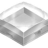
AT3074JD
Description
SW CAP SQ SW CAP CLEAR AMBER
Manufacturer
NKK Switches
Series
UB2r
Type
Cap, Sculptured for Illuminatedr
Specifications of AT3074JD
Switch Type
Pushbutton
Shape
Square, Sculptured
Color
Clear, Amber
Illumination
Illuminated
Mounting Type
Snap Fit
Size
15.00mm L x 15.00mm W x 6.10mm H
Height
6.1 mm
Length
15 mm
Mounting Style
SMD/SMT
Termination Style
Snap In
Width
15 mm
For Use With/related Products
UB2 Series
Lead Free Status / RoHS Status
Lead free / RoHS Compliant
For Use With
UB2 Series


AT4179
Round Cap for Bright LED
Polycarbonate
Colors: JB JC JD JF
Series: LB Panel Seal
AT4181
Splashproof Boot Assembly
Boot Material: Black silicon rubber
Hex Nut Material & Finish:
Nickel plated brass
O-ring Material: Natural rubber
Series: M P S WT
1. Install switch bushing into mounting hole of panel from the back and
2. Install o-ring on bushing and tighten nut from above.
3. Insert boot onto nut. Be sure the boot and nut are a firm, secure fit.
Use boot, nut and o-ring as shown. Use lockwasher and hexagon nut
(from standard switch hardware) behind panel.
adjust bushing to protrude 3.5 ~ 5.5mm (.138 ~ .217”).
Color Codes:
• M Series B2 Toggles with 12mm B1 & B3 Bushings
• P Series B Toggles with 12mm Bushing
• S31 ~ 39, S41 ~ 49, S31F ~ 33F, S41F ~ S43F, S31T ~ 33T, S41T ~ 43T
• S301 ~ 309, S331 ~ 339, S301F, S331F ~ 333F, S335F, S301T ~ 309T, S331T ~ 339T
• S421 ~ 429, S421T ~ 429
• WT11S ~ 29S, WT11T ~ 29T, WT11L ~ 29L
• S1A ~ 7A, S21A, S1F ~ 7F, S21F
• S114, S116
• S1AW ~ 9AW, S21AW, S25AW ~ 29AW
M, P or S Toggles with 12mm Bushings
(19.0) Dia
.748
(3.5) ~ (5.5)
.138 ~ .217
Switch Installation Instructions
Non-Splashproof Switches
.354
(9.0)
A Black
(24.3)
.957
B White
(18.6)
.732
Boot
(14.8)
Nut
.583
O-ring
Panel
Series or Part Numbers
(12.1) Dia
.476
C Red
(21.5) Dia
.846
AT4180
Snap-on Knob
Polyamide
Knob: Black
Flange: Transparent brown
Series: FR01
(8.0) Dia
.315
M12 P1
(17.5) Dia
.689
D Amber
.378
(9.6)
.039
(1.0)
www.nkk.com
Accessories & Hardware
(3.5) ~ (5.5)
.138 ~ .217
S1AW ~ S29AW S Toggles
1. Stretch base of the boot to fit around outer edges of the nut.
2. The ridge inside of boot must be firmly seated in groove of the nut.
3. Moving all around perimeter, push (with about 10N of force) toward
Use boot, nut and o-ring as shown. Use o-ring only (from standard switch
hardware) behind panel.
center to assure boot seals tightly into groove (with no air pockets).
E Yellow
1
.083
(0.8)
.031
(2.1)
For 12mm Bushings in M, P, S & WT Toggles
1
2
F Green
Boot & Nut Assembly Instructions
Boot
Nut
O-ring
Panel
Splashproof Switches
3
Panel Thickness (Maximum)
G Blue
WT Toggles or M Toggle with B3 Bushing
3
3
5.0mm (.197”)
3.5mm (.138”)
3.0mm (.118”)
(3.5) ~ (5.5)
.138 ~ .217
H Gray
3
3
J Clear
Boot
Nut
O-ring
Panel
3
Y33
Y
Related parts for AT3074JD
Image
Part Number
Description
Manufacturer
Datasheet
Request
R

Part Number:
Description:
Rocker Switches & Paddle Switches High In-rush Rated Rocker Switch
Manufacturer:
NKK Switches
Datasheet:
Part Number:
Description:
Rocker Switches & Paddle Switches High In-rush Rated Rocker Switch
Manufacturer:
NKK Switches
Datasheet:
Part Number:
Description:
Rocker Switches & Paddle Switches High In-rush Rated Rocker Switch
Manufacturer:
NKK Switches
Datasheet:
Part Number:
Description:
Rocker Switches & Paddle Switches High In-rush Rated Rocker Switch
Manufacturer:
NKK Switches
Datasheet:

Part Number:
Description:
Pushbutton Switches SPST ON(OFF) 15/32'
Manufacturer:
NKK Switches
Datasheet:

Part Number:
Description:
Pushbutton Switches SPST OFF(ON) 15/32'
Manufacturer:
NKK Switches
Datasheet:

Part Number:
Description:
Pushbutton Switches ON(OFF) NORM CLSD 3A RED PLNGR LUG 15/32
Manufacturer:
NKK Switches
Datasheet:

Part Number:
Description:
Pushbutton Switches SPDT ON-(ON)
Manufacturer:
NKK Switches
Datasheet:

Part Number:
Description:
Pushbutton Switches ON-(ON) RND BUSH MNT RED LED RED/RED CAP
Manufacturer:
NKK Switches
Datasheet:
Part Number:
Description:
Pushbutton Switches SPST ON-(OFF) STRT
Manufacturer:
NKK Switches
Datasheet:
Part Number:
Description:
Pushbutton Switches OFF(ON) NORM OPEN 3A RED CAP LUG 15/32
Manufacturer:
NKK Switches
Datasheet:
Part Number:
Description:
Pushbutton Switches ILLUM PUSHBUTTON SPDT
Manufacturer:
NKK Switches
Datasheet:
Part Number:
Description:
Pushbutton Switches OFF(ON) NORM OPEN 3A BLK CAP LUG 15/32
Manufacturer:
NKK Switches
Datasheet:
Part Number:
Description:
Pushbutton Switches SPST NO Metric Thrd Blk Plunge w/Blu Cap
Manufacturer:
NKK Switches
Datasheet: