A165L-TA Omron, A165L-TA Datasheet - Page 22
A165L-TA
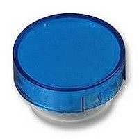
Manufacturer Part Number
A165L-TA
Description
CAP 16 SERIES ROUND BLUE
Manufacturer
Omron
Series
A16r
Specifications of A165L-TA
Switch Type
Pushbutton
Shape
Round
Color
Blue
Illumination
Illumination Optional
Mounting Type
Snap Fit
Size
15.10mm Dia x 3.50mm H
Svhc
No SVHC (15-Dec-2010)
Colour
Blue
External Diameter
15.1mm
Height
3.5mm
Panel Cutout Diameter
16mm
Mounting Hole Dia
16mm
Lens Colour
Blue
Lens Height
3.5mm
Lens Diameter
15.1mm
Rohs Compliant
Yes
For Use With
A16 Series Pushbutton Switches
Lead Free Status / RoHS Status
Lead free / RoHS Compliant
For Use With/related Products
A16 Series
Lead Free Status / Rohs Status
Lead free / RoHS Compliant
Other names
A165LTA


Dimensions
PCB Terminals (Lamp terminals are also present on non-lighted models.)
Terminal Arrangement
Voltage-reduction Lighting (Lamp terminals are also present on non-lighted models.)
Solder Terminals
• The voltage-reduction circuit is built in.
Note: Secure the panel to the board using stud bolts
A = 24 min.: Rectangular
A = 21 min.: Square or round
L = 24 min.
Use a PCB with a thickness of 1.6 mm.
(Bottom View)
PCB Cutouts
Dimensions of
PCB Terminals
2.7
if force will be applied to the board after wiring.
Lamp terminal (t=0.5)
0.8
1.5
DPDT lighted models
(Bottom view)
3.5
20 ± 0.1 4.85 ± 0.05
5.3
12.4 ± 0.05
Side with TOP indicated
Side with direction arrow
Five, 1 dia.
Model, rating, and lot
number indication
Lighted SPDT Switches
6.3 ± 0.05
NC
NO
C
L
L
4.85
12.4
18.6
NC
NO
C
Two, 5 dia.
Side with TOP indicated
A ± 0.1
Terminal Arrangement
(Bottom View)
Screw-Less Clamps
Red (Release button)
White (Release button)
Black (Release button)
Black (Release button)
• Voltage-reduction lighting models with Screw-Less Clamps (A16L-@T1-2S, A16L-@T2-2S)
incorporate voltage-reduction circuits.
COM
SW 1
NC
NO
L-
L ± 0.1
A = 24 min.: Rectangular
A = 21 min.: Square or round
L = 24 min.
Use a PCB with a thickness of 1.6 mm.
Note: Secure the panel to the board using stud bolts
Dimensions of
PCB Terminals
(Bottom View)
PCB Cutouts
Lamp terminal (t=0.5)
2.7
if force will be applied to the board after wiring.
0.8
1.5
3.5
20 ± 0.1
5.3
DPDT lighted models
Red (Release button)
12.4 ± 0.05
Black (Release button)
Side with TOP indicated
4.85 ± 0.05
Lighted DPDT Switches
12-3.1 dia. (Insertion hole)
Red (Release button)
White (Release button)
Black (Release button)
Black (Release button)
6.3 ± 0.05
4.85
12.4
18.6
Two, 5 dia.
Terminal Arrangement
Side with TOP indicated
(Bottom View)
6.3 ± 0.05
A ± 0.1
SW 1
COM
Side indicating TOP
NC
NO
NC2
NO2
C2
C2
L-
SW 2
COM
NC
NO
(Unit: mm)
-
+
+
A16
NC1
NO1
C1
C1
L ± 0.1
Eight, 1 d
22
Related parts for A165L-TA
Image
Part Number
Description
Manufacturer
Datasheet
Request
R

Part Number:
Description:
SWITCH PB SQ ALT DPDT GREEN
Manufacturer:
Omron
Datasheet:
Part Number:
Description:
SWITCH PB SQ MOM DPDT GREEN
Manufacturer:
Omron
Datasheet:
Part Number:
Description:
SWITCH PB SQ ALT DPDT RED
Manufacturer:
Omron
Datasheet:
Part Number:
Description:
SWITCH PB SQ MOM DPDT RED
Manufacturer:
Omron
Datasheet:
Part Number:
Description:
SWITCH PB SQ ALT DPDT WHITE
Manufacturer:
Omron
Datasheet:
Part Number:
Description:
SWITCH PB SQ MOM DPDT WHITE
Manufacturer:
Omron
Datasheet:
Part Number:
Description:
SWITCH PB SQ ALT DPDT YELLOW
Manufacturer:
Omron
Datasheet:
Part Number:
Description:
SWITCH PB SQ MOM DPDT YELLOW
Manufacturer:
Omron
Datasheet:
Part Number:
Description:
SWITCH PB RECT ALT DPDT GREEN
Manufacturer:
Omron
Datasheet:
Part Number:
Description:
SWITCH PB RECT MOM DPDT GREEN
Manufacturer:
Omron
Datasheet:
Part Number:
Description:
SWITCH PB RECT MOM DPDT RED
Manufacturer:
Omron
Datasheet:
Part Number:
Description:
SWITCH PB RECT ALT DPDT WHITE
Manufacturer:
Omron
Datasheet:
Part Number:
Description:
SWITCH PB RECT MOM DPDT WHITE
Manufacturer:
Omron
Datasheet: