AT204E NKK Switches, AT204E Datasheet - Page 32
AT204E
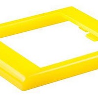
Manufacturer Part Number
AT204E
Description
SW CAP .787" BEZEL YELLOW
Manufacturer
NKK Switches
Type
Bezelr
Series
ATr
Specifications of AT204E
Color
Yellow
Height
2.2 mm
Length
25.5 mm
Mounting Style
Panel
Termination Style
Snap In
Width
20 mm
Lead Free Status / RoHS Status
Lead free / RoHS Compliant
For Use With
MLW Series


AT4179
Round Cap for Bright LED
Polycarbonate
Colors: JB JC JD JF
Series: LB Panel Seal
AT4181
Splashproof Boot Assembly
Boot Material: Black silicon rubber
Hex Nut Material & Finish:
Nickel plated brass
O-ring Material: Natural rubber
Series: M P S WT
1. Install switch bushing into mounting hole of panel from the back and
2. Install o-ring on bushing and tighten nut from above.
3. Insert boot onto nut. Be sure the boot and nut are a firm, secure fit.
Use boot, nut and o-ring as shown. Use lockwasher and hexagon nut
(from standard switch hardware) behind panel.
adjust bushing to protrude 3.5 ~ 5.5mm (.138 ~ .217”).
Color Codes:
• M Series B2 Toggles with 12mm B1 & B3 Bushings
• P Series B Toggles with 12mm Bushing
• S31 ~ 39, S41 ~ 49, S31F ~ 33F, S41F ~ S43F, S31T ~ 33T, S41T ~ 43T
• S301 ~ 309, S331 ~ 339, S301F, S331F ~ 333F, S335F, S301T ~ 309T, S331T ~ 339T
• S421 ~ 429, S421T ~ 429
• WT11S ~ 29S, WT11T ~ 29T, WT11L ~ 29L
• S1A ~ 7A, S21A, S1F ~ 7F, S21F
• S114, S116
• S1AW ~ 9AW, S21AW, S25AW ~ 29AW
M, P or S Toggles with 12mm Bushings
(19.0) Dia
.748
(3.5) ~ (5.5)
.138 ~ .217
Switch Installation Instructions
Non-Splashproof Switches
.354
(9.0)
A Black
(24.3)
.957
B White
(18.6)
.732
Boot
(14.8)
Nut
.583
O-ring
Panel
Series or Part Numbers
(12.1) Dia
.476
C Red
(21.5) Dia
.846
AT4180
Snap-on Knob
Polyamide
Knob: Black
Flange: Transparent brown
Series: FR01
(8.0) Dia
.315
M12 P1
(17.5) Dia
.689
D Amber
.378
(9.6)
.039
(1.0)
www.nkk.com
Accessories & Hardware
(3.5) ~ (5.5)
.138 ~ .217
S1AW ~ S29AW S Toggles
1. Stretch base of the boot to fit around outer edges of the nut.
2. The ridge inside of boot must be firmly seated in groove of the nut.
3. Moving all around perimeter, push (with about 10N of force) toward
Use boot, nut and o-ring as shown. Use o-ring only (from standard switch
hardware) behind panel.
center to assure boot seals tightly into groove (with no air pockets).
E Yellow
1
.083
(0.8)
.031
(2.1)
For 12mm Bushings in M, P, S & WT Toggles
1
2
F Green
Boot & Nut Assembly Instructions
Boot
Nut
O-ring
Panel
Splashproof Switches
3
Panel Thickness (Maximum)
G Blue
WT Toggles or M Toggle with B3 Bushing
3
3
5.0mm (.197”)
3.5mm (.138”)
3.0mm (.118”)
(3.5) ~ (5.5)
.138 ~ .217
H Gray
3
3
J Clear
Boot
Nut
O-ring
Panel
3
Y33
Y
Related parts for AT204E
Image
Part Number
Description
Manufacturer
Datasheet
Request
R

Part Number:
Description:
Switch Hardware AT SERIES CAP RECTANGULAR
Manufacturer:
NKK Switches
Datasheet:

Part Number:
Description:
Switch Hardware SQR SPOT ILLUM CAP YEL LED BLK CAP
Manufacturer:
NKK Switches
Datasheet:

Part Number:
Description:
Switch Hardware MOUNTING HRDWARE KIT M TN OPTION RKRS
Manufacturer:
NKK Switches
Datasheet:

Part Number:
Description:
Switch Hardware RED LED
Manufacturer:
NKK Switches
Datasheet:

Part Number:
Description:
Switch Hardware 4 ELEMENT LED RED 5V
Manufacturer:
NKK Switches
Datasheet:

Part Number:
Description:
Switch Hardware INCANDESCENT 12V
Manufacturer:
NKK Switches
Datasheet:

Part Number:
Description:
Switch Hardware ACTUATOR KEY FOR SK13 SERIES
Manufacturer:
NKK Switches
Datasheet:

Part Number:
Description:
Switch Hardware CAP
Manufacturer:
NKK Switches
Datasheet:

Part Number:
Description:
Switch Hardware WHITE CAP
Manufacturer:
NKK Switches
Datasheet:

Part Number:
Description:
ON-OFF PLATE - SERIES -EMP
Manufacturer:
NKK Switches
Datasheet:

Part Number:
Description:
WRENCH SOCKET FOR KB SERIES PB
Manufacturer:
NKK Switches
Datasheet:

Part Number:
Description:
SWITCH TOGGLE DPST 25A SLDR 5PCS
Manufacturer:
NKK Switches
Datasheet:

Part Number:
Description:
SWITCH TOGGLE DPDT 15A SLDR 5PC
Manufacturer:
NKK Switches
Datasheet:

Part Number:
Description:
SWITCH TOGGLE 4PST 25A SLDR 5PCS
Manufacturer:
NKK Switches
Datasheet: