A165-CTA Omron, A165-CTA Datasheet - Page 25
A165-CTA
Manufacturer Part Number
A165-CTA
Description
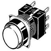
CASE ROUND 16 SERIES ALTERNATE
Manufacturer
Omron
Type
Pushbutton Round Caser
Specifications of A165-CTA
Illumination
Not Illuminated
Svhc
No SVHC (15-Dec-2010)
Approval Bodies
UL, CSA, IP65
Colour
Black
Contact Voltage Ac Max
250V
Contact Voltage Dc Max
30V
External Depth
28.5mm
External Diameter
18mm
External Length /
RoHS Compliant
Lead Free Status / RoHS Status
Lead free / RoHS Compliant
For Use With
A16/ M16 Series
Lead Free Status / RoHS Status
Lead free / RoHS Compliant
Other names
A165CTA


Screw-less Clamp Wiring Procedure
Connecting Wires
1. Strip the wires for 10 mm (allowable range: 10± 1 mm).
2. If braided wire is used, twist the wire to straighten it out.
3. Insert the wire into the insertion hole while pressing the release
4. Let go of the release button to lock the wire into place.
5. After locking, pull on the wire gently to confirm that it is securely
Removing Wires
1. Remove wires by pulling them while pressing the release button.
Note: When reusing wires that have already been locked one, cut off the end of
• Rubber is used inside IP65 models. Do not allow the rubber to
become scratched or foreign matter to become attached to the
rubber.
Scratches and foreign matter will degrade the waterproofing, and
the Switch may fail operate correctly.
button at the side of the hole. (Using a precision screwdriver is
recommended.)
locked.
the wire and strip the wire again before using.
Hammer
Screwdriver
Do not allow the Switch
to drop and hit the
ground.
Do not operate the Switch
with hard or sharp objects.
Do not place or drop
heavy objects on the
Switch.
Precautions
1. The mounting panel thickness must be 0.5 to 3.2 mm.
2. The mounting ring must be tightened to a torque 0.29 to 0.49 N·m.
3. The procedure for making the mounting hole for the screw-less
4. Be sure to mount the Case to the Switch with the correct
5. Bend the end of the wire if braided wire is used with the screw-
6. When wiring, insert the wire until it comes into contact with
7. After wiring, ensure that continuous pressure is not applied to the
8. Refer to internal connection diagrams and confirm the terminal
clamp connector is described on page 21. A mounting dimension
of at least 33 mm is required, however, because the Switch is
removed with the screw-less clamp connector mounted to the
panel. If Switches are mounted side-by-side separated by less
than the specified distance, it may not be possible to remove the
Switch.
orientation. Mount with the dimple on the Case facing in the same
direction as the side of the Switch with the direction arrow or the
word TOP.
less clamp connector.
something. After wiring is completed, pull on the wires to confirm
that they are connected securely.
terminals.
numbers before wiring.
Case
Case
dimple
dimple
Switch
Switch
TOP mark
Direction arrow
A16
25
Related parts for A165-CTA
Image
Part Number
Description
Manufacturer
Datasheet
Request
R

Part Number:
Description:
Switch, Pushbutton, NON-Illuminated, DPDT, Rectangular 2 SIDES GUARDED, GREEN, MOM.
Manufacturer:
Omron Automation
Datasheet:
Part Number:
Description:
Switch, Pushbutton, NON-Illuminated, DPDT, Rectangular 2 SIDES GUARDED, WHITE, MOM.
Manufacturer:
Omron Automation
Datasheet:
Part Number:
Description:
Switch, Pushbutton, NON-Illuminated, DPDT, Rectangular 2 SIDES GUARDED, GREEN, ALTERN.
Manufacturer:
Omron Automation
Datasheet:
Part Number:
Description:
Switch, Pushbutton, NON-Illuminated, DPDT, ROUND EXTENDED, GREEN, Momentary
Manufacturer:
Omron Automation
Datasheet:
Part Number:
Description:
Switch, Pushbutton, NON-Illuminated, DPDT, ROUND EXTENDED, WHITE, Momentary
Manufacturer:
Omron Automation
Datasheet:
Part Number:
Description:
Switch, Pushbutton, NON-Illuminated, DPDT, ROUND EXTENDED, RED, Momentary
Manufacturer:
Omron Automation
Datasheet:
Part Number:
Description:
Switch, Pushbutton, NON-Illuminated, DPDT, SQUARE 2 SIDES GUARDED, GREEN, Momentary
Manufacturer:
Omron Automation
Datasheet:
Part Number:
Description:
Switch, Pushbutton, NON-Illuminated, DPDT, ROUND EXTENDED, YELLOW, Momentary
Manufacturer:
Omron Automation
Datasheet:
Part Number:
Description:
Switch, Pushbutton, NON-Illuminated, DPDT, ROUND EXTENDED, BLACK, Momentary
Manufacturer:
Omron Automation
Datasheet:
Part Number:
Description:
Switch, Pushbutton, NON-Illuminated, DPDT, Rectangular 2 SIDES GUARDED, RED, MOM.
Manufacturer:
Omron Automation
Datasheet:
Part Number:
Description:
Switch, Pushbutton, NON-Illuminated, DPDT, SQUARE 2 SIDES GUARDED, RED, ALTERNATE
Manufacturer:
Omron Automation
Datasheet:
Part Number:
Description:
Switch, Pushbutton, NON-Illuminated, DPDT, SQUARE 2 SIDES GUARDED, WHITE, Momentary
Manufacturer:
Omron Automation
Datasheet:
Part Number:
Description:
Switch, Pushbutton, NON-Illuminated, DPDT, SQUARE 2 SIDES GUARDED, YELLOW, Momentary
Manufacturer:
Omron Automation
Datasheet:
Part Number:
Description:
Switch, Pushbutton, NON-Illuminated, DPDT, ROUND EXTENDED, BLUE, Momentary
Manufacturer:
Omron Automation
Datasheet:
Part Number:
Description:
Switch, Pushbutton, NON-Illuminated, DPDT, Rectangular 2 SIDES GUARDED, YELLOW, MOM.
Manufacturer:
Omron Automation
Datasheet: