AT701 NKK Switches, AT701 Datasheet - Page 4
AT701
Manufacturer Part Number
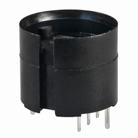
AT701
Description
ADAPTER STRAIGHT PC SP KB SERIES
Manufacturer
NKK Switches
Type
PCB Adapter, Single Pole Straightr
Series
ATr
Specifications of AT701
Height
9.8 mm
Mounting Style
Through Hole
Termination Style
Solder
Width
12 mm
Lead Free Status / RoHS Status
Lead free / RoHS Compliant
For Use With
KB Series


D
Series KB
D26
Pole
DP
SP
S
K
K
Keyway
Without
Housing available in black only. Bezel or barrier is an integral part of the switch body.
.551” (14.0mm)
Square
.551” (14.0mm)
Square
No barrier
No barrier
* KB16
* KB26
Model
KB15
KB25
Panel thicknesses, when using optional accessories, are shown with the accessories at the end of this KB section.
* When in latchdown position for the alternate circuit, cap position is .055” (1.4mm) above the built-in bezel.
Bezel or barrier is an integral part of the switch body. One mounting nut AT057 supplied with each switch.
Normal
( ) = Momentary
Plunger Position
ON
ON
ON
ON
(12.3) Dia
.484
With barrier
With barrier
Bushing Mounting
Panel Thickness:
(0.5 ~ 8.0mm)
.020” ~ .315”
Down
(ON)
(ON)
ON
ON
Bezel or barrier is an integral part of the switch body.
MOUNTING TYPES & SHAPES
2-3 5-6
Normal
Connected Terminals
M
C
2-3
POLES & CIRCUITS
www.nkk.com
.551” (14.0mm)
Round
.551” (14.0mm)
Round
Bushing Mounting
Snap-in Mounting
HOUSING
Panel Cutouts
2-1 5-4
Down
(12.3) Dia
.484
2-1
(4.9)
.193
With
Keyway
Notes:
SPDT
DPDT
3
Throw & Switch/Lamp Schematics
Switch is marked with “+” and “–”.
Lamp circuit is isolated and requires
external power source.
3
N
R
2
Panel Thickness:
(1.0 ~ 3.5mm)
.039” ~ .138”
(COM)
1
Miniature Pushbuttons
.551” x .728” (14.0mm x 18.5mm)
Rectangular
.551” x .728” (14.0mm x 18.5mm)
Rectangular
2 (COM)
6
No barrier
No barrier
1
5
Snap-in Mounting
4
.047
(1.2) R
L (+)
L (+)
.268
(6.8)
With barrier
With barrier
(12.3) Dia
.484
(-) L
(-) L
Related parts for AT701
Image
Part Number
Description
Manufacturer
Datasheet
Request
R

Part Number:
Description:
Rocker Switches & Paddle Switches High In-rush Rated Rocker Switch
Manufacturer:
NKK Switches
Datasheet:
Part Number:
Description:
Rocker Switches & Paddle Switches High In-rush Rated Rocker Switch
Manufacturer:
NKK Switches
Datasheet:
Part Number:
Description:
Rocker Switches & Paddle Switches High In-rush Rated Rocker Switch
Manufacturer:
NKK Switches
Datasheet:
Part Number:
Description:
Rocker Switches & Paddle Switches High In-rush Rated Rocker Switch
Manufacturer:
NKK Switches
Datasheet:

Part Number:
Description:
Pushbutton Switches SPST ON(OFF) 15/32'
Manufacturer:
NKK Switches
Datasheet:

Part Number:
Description:
Pushbutton Switches SPST OFF(ON) 15/32'
Manufacturer:
NKK Switches
Datasheet:

Part Number:
Description:
Pushbutton Switches ON(OFF) NORM CLSD 3A RED PLNGR LUG 15/32
Manufacturer:
NKK Switches
Datasheet:

Part Number:
Description:
Pushbutton Switches SPDT ON-(ON)
Manufacturer:
NKK Switches
Datasheet:

Part Number:
Description:
Pushbutton Switches ON-(ON) RND BUSH MNT RED LED RED/RED CAP
Manufacturer:
NKK Switches
Datasheet:
Part Number:
Description:
Pushbutton Switches SPST ON-(OFF) STRT
Manufacturer:
NKK Switches
Datasheet:
Part Number:
Description:
Pushbutton Switches OFF(ON) NORM OPEN 3A RED CAP LUG 15/32
Manufacturer:
NKK Switches
Datasheet:
Part Number:
Description:
Pushbutton Switches ILLUM PUSHBUTTON SPDT
Manufacturer:
NKK Switches
Datasheet:
Part Number:
Description:
Pushbutton Switches OFF(ON) NORM OPEN 3A BLK CAP LUG 15/32
Manufacturer:
NKK Switches
Datasheet:
Part Number:
Description:
Pushbutton Switches SPST NO Metric Thrd Blk Plunge w/Blu Cap
Manufacturer:
NKK Switches
Datasheet:
Part Number:
Description:
Pushbutton Switches SPST OFF-(ON) NO 3A
Manufacturer:
NKK Switches
Datasheet: