AT433A NKK Switches, AT433A Datasheet - Page 4
AT433A
Manufacturer Part Number
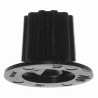
AT433A
Description
SWITCH MINI KNOB BLCK FR/MR SER
Manufacturer
NKK Switches
Series
ATr
Type
Knobr
Specifications of AT433A
Accessory Type
Knob
Design
Ribbed with Skirt
Shaft Size
13 mm
Diameter
11 mm
Color
Black
Indicator Style
Line
Switch Type
Rotary Switch
Operating Temp Range
-10C to 70C
For Use With/related Products
FR and MR Series
For Use With
MRY106G-CG - SW ROTARY ACTUATOR SP 2-6PS GOLDMRY106G-A - SW ROTARY ACTUATOR SP 2-6PS GOLDMRY106-CH - SW ROTARY ACTUATOR SP 2-6POSMRX204-BG - SW ROTARY ACTUATOR DP 2-4POSMRX108-CE - SW ROTARY ACTUATOR SP 2-8POSMRX108-CA - SW ROTARY ACTUATOR SP 2-8POS360-2375 - SW ROTARY ACTUATOR DPDT BLACKMRK206-CC - SW ROTARY ACTUATOR DP 2-6 POSMRK112-CH - SW ROTARY ACTUATOR SP 2-12POSMRA403 - SW ROTARY ACTUATOR 4P 2-3POSMRA403-BA - SW ROTARY ACTUATOR 4P 2-3POSMRA206-CB - SW ROTARY ACTUATOR DP 2-6POSMRA206-BH - SW ROTARY ACTUATOR DP 2-6POSMRA206-BF - SW ROTARY ACTUATOR DP 2-6POSMRA206-BC - SW ROTARY ACTUATOR DP 2-6POSMRA206-BB - SW ROTARY ACTUATOR DP 2-6POSMRA112-BA - SW ROTARY ACTUATOR SP 2-12POSMRA112/208 - SW ROTARY ACTUATOR SP 2-12POSFR01AR16PB-W-S - SWITCH ROTARY 16POS STR T/H WASHFR01AR16PB - SWITCH ROTARY 16POS STRGHT T/HFR01AR16HB-06XL-W-S - SW ROTARY 16PS R/A .2" T/H WASHFR01AR16HB-06XL-S - SWITCH ROTARY 16POS R/A .2" T/HFR01AR16HB-06XL - SWITCH ROTARY 16POS R/A .2" T/HFR01AR16HB - SWITCH ROTARY 16POS RT ANG T/HFR01AR10PB-W-S - SWITCH ROTARY 10POS STR T/H WASHFR01AR10PB - SWITCH ROTARY 10POS STR T/HFR01AR10HB - SWITCH ROTARY 10PS RT ANG T/HFR01AC10PB-W-S - SWITCH ROTARY 10POS STR T/H WASHFR01AC10PB-W - SWITCH ROTARY 10PS STR T/H WASHFR01AC10PB - SWITCH ROTARY 10POS STR T/HFR01AR16PB-S - SW ROTARY DIP HEX RED STRT BRKTFR01AR16HB-S - SW ROTARY DIP HEX RED RA BRKTFR01AR10PB-S - SW ROTARY DIP DEC RED STRT BRKTFR01AR10HB-S - SW ROTARY DIP DEC RED RA BRKTFR01AC16PB-S - SW ROTARY DIP HEX YEL STRT BRKTFR01AC16HB-S - SW ROTARY DIP HEX YEL RA BRKTFR01AC10PB-S - SW ROTARY DIP DEC YEL STRT BRKT360-2369 - SW ROTARY DP 2-6POS BLK KNOB PCMRA112-BB - SW ROTARY SP WHT TIP SM KNOB PC360-2368 - SW ROTARY SP 2-12POS BLK KNOB PCMRX402-A - SW ROTARY 4P BK KNOB PC TURRETMRA206 - SW ROTARY DP 2-6POS PCMRA112-CC - SW ROTARY SP RED TIP LG KNOB PCMRA403-A - SW ROTARY 4P 2-3POS BK KNOB PCMRX402-CA - SW ROTARY 4P BK TIP LG KNOB PCMRK112-BG - SW ROTARY SP BLUE TIP SM KNOB PCMRX204 - SW ROTARY DP PC TURRET360-2374 - SW ROTARY 4P 2-3POS BLK KNOB PC360-2377 - SW ROTARY SP BLK KNOB PC TURRETMRK112-BH - SW ROTARY SP GRY TIP SM KNOB PC360-2373 - SW ROTARY DP 2-6POS BLK KNOB PC360-2379 - SW ROTARY SP BLK KNOB TURRETMRK403-BB - SW ROTARY 4P WHT TIP SM KNOB PCMRX108-BC - SW ROTARY SP RD TIP LG KNOB PCMRA112 - SW ROTARY SP 2-12POS PCMRK206-BB - SW ROTARY DP WHT TIP SM KNOB PCMRY106-BC - SW ROTARY SP RED TIP SM KNOB360-2378 - SW ROTARY DP BLK KNOB PC TURRETMRA403-BG - SW ROTARY 4P BLU TIP SM KNOB PCMRK112 - SW ROTARY SP 2-12POS BK KNOB PCMRT23-BB - SW ROTARY DP WH SM TIP KNOB SLD360-2372 - SW ROTARY SP 2-12POS BLK KNOB PCMRY106 - SW ROTARY SP TURRET TERMMRK206 - SW ROTARY DP 2-6POS PCMRT23 - SW ROTARY DPDT SOLDER LUG360-2376 - SW ROTARY DPDT BLK KNOB SLD LUGMRK206-BC - SWITCH ROTARY DP6T PC MNTMRK112-BB - SWITCH ROTARY SP12T LOPRO PC MNT
Lead Free Status / RoHS Status
Lead free / RoHS Compliant
Other names
360-2410
AT433A
AT433A


Half-Inch Diameter Process Sealed Rotaries
Each switch is supplied with the stopper set for the maximum number of positions allowed for that model. Prior to installation,
the desired position setting should be made. Contact factory for continuous rotation.
1. Remove the protective cover from the switch body.
2. Turn the shaft counterclockwise to the extreme left by using a screwdriver.
3. Inside the cover is a magnifying lens which would be positioned over the
1. Using the actuator knob, turn the shaft
2. Remove the knob from the shaft and
3. Note the position numbers on the side
4. Tighten the nut (beveled side up) firmly
Pole
DP
SP
4P
number which is to be the maximum position used; when the cover is then
snapped into the switch, the projection beside the lens fits into the correct
hole for setting the stop.
counterclockwise to the extreme left. If
the shaft is not turned counterclockwise
to the extreme left, proper setting can-
not be achieved. At this extreme posi-
tion, the white line on the knob points
to the number 1 position shown on the
side of the switch.
loosen the nut far enough to allow rais-
ing the stopper plate, plus washer(s),
for resetting to the desired position.
of the switch; these correspond to the
terminal numbers and stopper holes.
Insert the stopper in the hole numbered
for the maximum desired number of
stop settings. Satisfactory switch func-
tioning cannot be assured if the stopper
plate is not properly positioned.
against the stopper plate.
MRA112
MRA206
MRA403
MRK112
MRK206
MRK403
MRF112
MRF206
MRF403
Model
MRK & MRA Models
Number of Positions
POSITION SETTING FOR MRA, MRF, & MRK MODELS
2–12
2–12
2–12
2–6
2–6
2–6
2–3
2–3
2–3
MRF Models
Stopper Settings
2, 3, 4, . . . 12
2, 3, 4, . . . 12
2, 3, 4, . . . 12
2, 3, 4, 5, 6
2, 3, 4, 5, 6
2, 3, 4, 5, 6
POLES & CIRCUITS
2, 3
2, 3
2, 3
1 C
11
12
www.nkk.com
Number of Terminals
1 COM, 12 LOAD
1 COM, 12 LOAD
1 COM, 12 LOAD
2 COM, 12 LOAD
2 COM, 12 LOAD
2 COM, 12 LOAD
4 COM, 12 LOAD
4 COM, 12 LOAD
4 COM, 12 LOAD
Packaged Loose with Each Switch:
Standard Mounting Hardware
Metal Washer (MRA)
Factory Assembled:
Rubber Ring (MRK)
Rubber Washer
Hex Face Nut
Stopper Plate
Locking Ring
Lockwasher
Hex Nut
Protective Cover
1 2 3 4 5 6 7 8 9 10 11 12
1 2 3 4 5 6 1
1 2 3 1
A
Series MR
1 C
A
12
Schematics
2 3 1
B
A
Lens
Projection
1
2 3 4 5 6
2 3 1
C
12
11
B
9
2 3
D
G19
G
Related parts for AT433A
Image
Part Number
Description
Manufacturer
Datasheet
Request
R

Part Number:
Description:
Switch Hardware AT SERIES CAP RECTANGULAR
Manufacturer:
NKK Switches
Datasheet:

Part Number:
Description:
Switch Hardware SQR SPOT ILLUM CAP YEL LED BLK CAP
Manufacturer:
NKK Switches
Datasheet:

Part Number:
Description:
Switch Hardware MOUNTING HRDWARE KIT M TN OPTION RKRS
Manufacturer:
NKK Switches
Datasheet:

Part Number:
Description:
Switch Hardware RED LED
Manufacturer:
NKK Switches
Datasheet:

Part Number:
Description:
Switch Hardware 4 ELEMENT LED RED 5V
Manufacturer:
NKK Switches
Datasheet:

Part Number:
Description:
Switch Hardware INCANDESCENT 12V
Manufacturer:
NKK Switches
Datasheet:

Part Number:
Description:
Switch Hardware ACTUATOR KEY FOR SK13 SERIES
Manufacturer:
NKK Switches
Datasheet:

Part Number:
Description:
Switch Hardware CAP
Manufacturer:
NKK Switches
Datasheet:

Part Number:
Description:
Switch Hardware WHITE CAP
Manufacturer:
NKK Switches
Datasheet:

Part Number:
Description:
ON-OFF PLATE - SERIES -EMP
Manufacturer:
NKK Switches
Datasheet:

Part Number:
Description:
WRENCH SOCKET FOR KB SERIES PB
Manufacturer:
NKK Switches
Datasheet:

Part Number:
Description:
SWITCH TOGGLE DPST 25A SLDR 5PCS
Manufacturer:
NKK Switches
Datasheet:

Part Number:
Description:
SWITCH TOGGLE DPDT 15A SLDR 5PC
Manufacturer:
NKK Switches
Datasheet:

Part Number:
Description:
SWITCH TOGGLE 4PST 25A SLDR 5PCS
Manufacturer:
NKK Switches
Datasheet: