947705-001 Grayhill Inc, 947705-001 Datasheet - Page 3
947705-001
Manufacturer Part Number
947705-001
Description
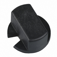
KNOB BLACK WINDOW VERSION 94 SER
Manufacturer
Grayhill Inc
Type
Knobr
Specifications of 947705-001
Accessory Type
Knob - Black
Knob / Dial Style
Round With Notch
Knob Diameter
9.4mm
External Height
5.93mm
Peak Reflow Compatible (260 C)
Yes
Leaded Process Compatible
No
Shaft Size
3.56 Mm
Color
Black
Switch Type
DIP Switch
Operating Temp Range
-40C to 85C
Lead Free Status / RoHS Status
Lead free / RoHS Compliant
For Use With/related Products
Extended Actuators Only
For Use With
GH7263 - SWITCH HEX ROTARY DIP THRUHOLEGH7262 - SWITCH HEX ROTARY DIP RT ANGLEGH7261 - SWITCH BCD ROTARY DIP THRUHOLEGH7260 - SWITCH BCD ROTARY DIP RT ANGLEGH7258 - SWTCH OCTAL ROTARY DIP THRU HOLEGH7257 - SWITCH OCTAL ROTARY DIP RT ANGLEGH1323 - SWITCH HEX ROTARY DIP RT ANGLEGH1321 - SWITCH HEX ROTARY DIP PC MNTGH1318 - SWITCH BCD ROTARY DIP RT ANGLEGH1316 - SWITCH BCD ROTARY DIP PC MNTGH1313 - SWITCH OCTAL ROTARY DIP RT ANGGH1311 - SWITCH OCTAL ROTARY DIP PC MNT
Lead Free Status / Rohs Status
Not Compliant
Other names
947701-001
GH5005
GH5005
Available stocks
Company
Part Number
Manufacturer
Quantity
Price
Company:

Part Number:
947705-001
Manufacturer:
GHY
Quantity:
1 790


SERIES 94R
Economical, Binary Coded
DIMENSIONS
SPECIFICATIONS:
Electrical Ratings
Make-and-break Current Rating: 30 mA at 30
Vdc for 10,000 cycles of operation.
Carrying Current Rating: 100 mA at 50 Vdc
Contact Resistance: 50 mohms maximum
initially (measured at 10 mA, 50 mVdc).
150 mohms maximum after life.
Insulation Resistance:(measured at 100 Vdc
across open switch contacts)
Initial: 5000 Mohms minimum. After Life: 1000
Mohms minimum.
Dielectric Strength: (measured across open
switch contacts) Initial: 500 Vac RMS
minimum. After Life: 250 Vac RMS
Mechanical Ratings
Mechanical Life: 10,000 cycles of operation.
One cycle is a rotation through all positions and
a complete return through all positions.
Mechanical Shock: 1000g's, 0.5 mS, half sine per
MIL-STD-202F, Method 213, Test Condition E.
Vibration Resistance: 10-2000 Hz at 15G or
0.060" double amplitude per MIL-STD-202F,
Method 204, Test Condition B.
Operational Torque: 2 to 6 inch-ounces initially
and 1.2 inch-ounces minimum after life.
B-23
Unless otherwise indicated, tolerances are ± .010 (0,25)
Grayhill, Inc. • 561 Hillgrove Avenue • LaGrange, Illinois 60525-5997 • USA • Phone: 708-354-1040 • Fax: 708-354-2820 • www.grayhill.com
In inches (and millimeters)
PC board layout
as viewed from the
top of the switch
Series 94H and 94R
Rotary DIP Switches
(11,00)
1
C
4
.433
8
C
2
(5,41)
.213
FEATURES
• 10,000 Cycles of Operation
• Gold-Plated Contacts
• Sealed Contact System
• Right Angle Mount
• Octal, BCD & Hexadecimal Codes
• Standard or Complement
Environmental Ratings
Operating Temperature Range: -40° to +85°C.
Storage Temperature Range: -40° to +85°C.
Moisture Resistance: 240 hours with
temperature cycling and polarization. Passes
insulation resistance and dielectric strength
per MIL-STD-202F, Method 106 following
exposure.
Materials and Finishes
Rotor and Switch Body: Plastic (UL94V-O)
Contact Material: Copper alloy plated.
30 microinches minimum gold over 50
microinches minimum nickel.
Shorting Member: Copper alloy plated.
30 microinches minimum gold over 50
microinches minimum nickel.
Terminals: Copper alloy plated. 100
microinches minimum 90/10 tin lead solder
over 50 microinches minimum nickel.
Internal O-ring: Rubber BUNA-N
Soldering Information
Soldering Temperature: 250° C for 10 seconds
maximum.
Cleaning: Acceptable solutions include 1-1-1
Trichlorenthane, Freon (TF, TE, or TMS),
Isopropyl Alcohol and detergent (140°F
maximum). Solutions which are not
recommended include Acetone, Methylene
Chloride, and Freon TMC.
(7,26)
.286
(1,50)
.059
(4,55)
.179
.058 (1,47)
.044 (1,12)
DIA.
DIA.
.689 (17,50)
1.123 (28,52)
CODE & TRUTH TABLES:
Series 94H and 94R
Standard
Output
Dot indicates terminal to common
connection. All switches are continuous
rotation.
Octal and Octal Complement outputs are 0
thru 7 positions.
BCD and BCD Complement outputs are 0
thru 9 positions.
H e x a d e c i m a l
Complement outputs are 0 thru F positions.
Standard codes have natural color
rotors; complements have rotors in a
contrasting color.
.199 (5,05)
.235 (5,97)
A
B
C
D
E
F
0
1
2
3
4
5
6
7
8
9
(11,25)
.443
.200 (5,08)
CODE OUTPUT
1 2
Pin #1
(12,19)
4
.480
a n d
8
CODE OUTPUT
1 2
H e x a d e c i m a l
4
8
Complement
Output
Related parts for 947705-001
Image
Part Number
Description
Manufacturer
Datasheet
Request
R

Part Number:
Description:
KNOB GRAY WINDOW VERSION 94 SER
Manufacturer:
Grayhill Inc
Datasheet:

Part Number:
Description:
Switch Knob
Manufacturer:
Grayhill Inc
Datasheet:

Part Number:
Description:
Rotary DIP Switch, Actuator Knob, Gray
Manufacturer:
Grayhill Inc
Datasheet:

Part Number:
Description:
Rotary DIP Switch, Actuator Knob, Gray
Manufacturer:
Grayhill Inc
Datasheet:
Part Number:
Description:
Rotary DIP Switch, Actuator Knob, Gray
Manufacturer:
Grayhill Inc
Datasheet:
Part Number:
Description:
Rotary DIP Switch, Actuator Knob, Natural
Manufacturer:
Grayhill Inc
Datasheet:
Part Number:
Description:
Rotary DIP Switch, Actuator Knob, Black
Manufacturer:
Grayhill Inc
Datasheet:
Part Number:
Description:
Rotary DIP Switch, Actuator Knob, Gray
Manufacturer:
Grayhill Inc
Datasheet:
Part Number:
Description:
Rotary DIP Switch, Actuator Knob, Gray
Manufacturer:
Grayhill Inc
Datasheet:
Part Number:
Description:
Rotary DIP Switch, Actuator Knob, Gray
Manufacturer:
Grayhill Inc
Datasheet:
Part Number:
Description:
Rotary DIP Switch, Actuator Knob, Black
Manufacturer:
Grayhill Inc
Datasheet:
Part Number:
Description:
Rotary DIP Switch, Actuator Knob, Black
Manufacturer:
Grayhill Inc
Datasheet:
Part Number:
Description:
Encoder; 32pos; custom switching; sealed; continous rotation;
Manufacturer:
Grayhill Inc
Part Number:
Description:
50EPT90-01-1-04N-C SINGLE DECK ROTARY 0.5(12.7mm)DIA,200mA,Continuous
Manufacturer:
Grayhill Inc