A16-1P Omron, A16-1P Datasheet - Page 24
A16-1P
Manufacturer Part Number
A16-1P
Description
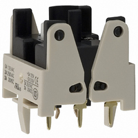
SWTCH BLOCK SPDT PCB TERMINAL
Manufacturer
Omron
Type
Pushbuttonr
Datasheet
1.A16-5DSG.pdf
(28 pages)
Specifications of A16-1P
Accessory Type
Switch Block Replacement
Mounting Style
PCB
Termination Style
Solder
For Use With/related Products
A16 Series
For Use With
Z1398 - SWTCH KNOB RND 3POS DPDT ILL YLWZ1397 - SWTCH KNOB RND 3POS DPDT ILL REDZ1396 - SWTCH KNOB RND 3POS DPDT ILL GRNZ1395 - SWTCH KNOB RND 2POS SPDT ILL YLWZ1394 - SWTCH KNOB RND 2POS SPDT ILL REDZ1393 - SWTCH KNOB RND 2POS SPDT ILL GRNZ1392 - SWTCH KNOB RND 2POS SPDT ILL YLWZ1391 - SWTCH KNOB RND 2POS SPDT ILL REDZ1390 - SWTCH KNOB RND 2POS SPDT ILL GRNZ1389 - SWITCH KNOB RND 3-POS DPDTZ1388 - SWITCH KNOB RND 2-POS SPDTZ1387 - SWITCH KNOB RND 2-POS SPDTZ1386 - SWITCH KNB RECT 3POS DPDT ILLZ1385 - SWITCH KNB RECT 3POS DPDT ILLZ1384 - SWITCH KNB RECT 3POS DPDT ILLZ1383 - SWITCH KNB RECT 2POS SPDT ILLZ1382 - SWITCH KNB RECT 2POS SPDT ILLZ1381 - SWITCH KNB RECT 2POS SPDT ILLZ1380 - SWITCH KNB RECT 2POS SPDT ILLZ1379 - SWITCH KNB RECT 2POS SPDT ILLZ1378 - SWITCH KNB RECT 2POS SPDT ILLZ1377 - SWITCH KNOB RECT 3-POS DPDTZ1376 - SWITCH KNOB RECT 2-POS SPDTZ1375 - SWITCH KNOB RECT 2-POS SPDTZ1374 - SWITCH KNOB SQ 3-POS DPDT ILLZ1373 - SWITCH KNOB SQ 3-POS DPDT ILLZ1372 - SWITCH KNOB SQ 3-POS DPDT ILLZ1371 - SWITCH KNOB SQ 2-POS SPDT ILLZ1370 - SWITCH KNOB SQ 2-POS SPDT ILLZ1369 - SWITCH KNOB SQ 2-POS SPDT ILLZ1368 - SWITCH KNOB SQ 2-POS SPDT ILLZ1367 - SWITCH KNOB SQ 2-POS SPDT ILLZ1366 - SWITCH KNOB SQ 2-POS SPDT ILLZ1365 - SWITCH KNOB SQ 3-POS DPDTZ1364 - SWITCH KNOB SQ 2-POS SPDTZ1363 - SWITCH KNOB SQ 2-POS SPDTZ1328 - SWITCH PB ROUND MOM SPDT YELLOWZ1327 - SWITCH PB ROUND MOM SPDT WHITEZ1326 - SWITCH PB ROUND MOM SPDT REDZ1325 - SWITCH PB ROUND MOM SPDT GREENZ1324 - SWITCH PB ROUND MOM SPDT BLACKZ1323 - SWITCH PB ROUND MOM SPDT BLUEZ1322 - SWITCH PB RECT MOM DPDT YELLOWZ1321 - SWITCH PB RECT MOM DPDT WHITEZ1320 - SWITCH PB RECT MOM DPDT REDZ1319 - SWITCH PB RECT MOM DPDT GREENZ1318 - SWITCH PB RECT MOM DPDT BLACKZ1317 - SWITCH PB SQUARE MOM DPDT YELLOWZ1316 - SWITCH PB SQUARE MOM DPDT WHITEZ1315 - SWITCH PB SQUARE MOM DPDT REDZ1314 - SWITCH PB SQUARE MOM DPDT GREENZ1313 - SWITCH PB SQUARE MOM DPDT BLACKZ1312 - SWITCH PB SQUARE MOM DPDT BLUEZ1311 - SWITCH PB RND MOM DPDT ILLUM YLWZ1310 - SWITCH PB RND MOM DPDT ILLUM WHTZ1309 - SWITCH PB RND MOM DPDT ILLUM REDZ1308 - SWITCH PB RND MOM DPDT ILLUM GRNZ1307 - SWITCH PB RECT MOM DPDT ILLUMZ1306 - SWITCH PB RECT MOM DPDT ILLUMZ1305 - SWITCH PB RECT MOM DPDT ILLUMZ1304 - SWITCH PB RECT MOM DPDT ILLUMZ1303 - SWITCH PB SQ MOM DPDT ILLUM YLLWZ1302 - SWITCH PB SQ MOM DPDT ILLUM WHTZ1301 - SWITCH PB SQ MOM DPDT ILLUM REDZ1300 - SWITCH PB SQ MOM DPDT ILLUM GRN
Lead Free Status / RoHS Status
Lead free / RoHS Compliant
Lead Free Status / RoHS Status
Lead free / RoHS Compliant, Lead free / RoHS Compliant
Other names
A161P
Z1332
Z1332


Safety Precautions
Refer to Safety Precautions for All Pushbutton Switches.
Do not apply a voltage between the incandescent
lamp and the terminal that is greater than the rated
voltage. If the incandescent lamp is broken, the
operating part may pop out.
Always turn OFF the power and wait for 10 minutes
before replacing the incandescent lamp. If the lamp is
replaced immediately after the power is turned OFF,
the remaining heat may cause burns.
Mounting
Wiring
Operating Environment
• Always make sure that the power is turned OFF before mounting,
• Do not tighten the mounting nut more than necessary using tools
• Solder terminals and quick-connect terminals (#110) are commonly
• Be sure to use electrical wires that are a size appropriate for the
• Use non-corrosive resin fluid as the flux.
• Make sure that the electric cord is wired so that it does not touch
• After wiring the Switch, maintain an appropriate clearance and
• This Switch is intended for indoor use only. Using the Switch
• The IP65 model is designed with a degree of protection so that it
• Do not use the Switch submersed in oil or water, or in locations
removing, or wiring the Switch, or performing maintenance.
such as pointed-nose pliers. Doing so will damage the mounting
nut.
The tightening torque is 0.29 to 0.49 N·m.
used for terminals.
applied voltage and carry current (conductor size is 0.5 to 0.75
mm
below. If the soldering is not properly performed, the lead wires will
become detached, resulting in short-circuits.
the Unit. If the electric cord touches the Unit, then electric wires with
a heat resistance of 100°C min. must be used.
creepage distance.
outdoors will cause the Switch to fail. If IP40 models are used in
locations subject to dust, metallic particles, or oil, be careful that
none of these penetrates the Switch.
will not sustain damage if it is subjected to water from any direction
to the front of the panel.
continuously subject to splashes of oil or water. Doing so may result
in oil of water entering the Switch.
1. Hand soldering: 350°C, within 3 s
2. Dip soldering: 350°C, within 3 s
Wait for one minute after soldering before exerting any external
force on the solder.
2
). Perform soldering according to the conditions provided
Precautions for Correct Use
WARNING
Using the Microload
LED
Others
• Insert a contact protection circuit, if necessary, to prevent the
• The A16 allows both a standard load (125 V at 5A, 250 V at 3 A)
• The minimum applicable load is the N-level reference value. This
• The LED current-limiting resistor is built-in, so external resistance
• The oil-resistant IP65 uses NBR rubber and is resistant to general
• The durability of the Switch depends in the switching conditions.
• If the panel is to be finished with coating, etc., make sure that the
• Do not subject the Switch to extreme shock or vibration. Doing so
• Do not let sharp objects come into contact with the Switches that
Rated voltage
12 VAC/VDC
24 VAC/VDC
reduction of life expectancy due to extreme wear on the contacts
caused by loads where inrush current occurs when the contact is
opened and closed.
and a microload. If a standard load is applied, however, the
microload area cannot be used. If the microload area is used with a
standard load, the contact surface will become rough, and the
opening and closing of the contact for a microload may become
unreliable.
value indicates the malfunction reference level for the reliability
level of 60% (λ 60) (conforming to JIS C5003).
The equation, λ 60 = 0.5 × 10
estimated malfunction rate is less than 1/2,000,000 operations with
a reliability level of 60%.
is not required.
cutting oil and cooling oil. Some particular oils cannot be used with
the oil-resistant IP65, however, so contact your OMRON
representative for details.
Always test the Switch under actual application conditions to
confirm applicability and use the Switch only for the number of
switching operations that will not affect performance.
Continuing to use the Switch with degraded performance will
eventually result insulation faults between circuits, burning of the
Switch, or other failures.
panel meets the specified dimensions after the coating.
will cause malfunctions and damage to the Switch.
are made of resin. Doing so will damage the Switches, causing
scratches on the outside of the operating parts, and malfunction.
When handling the Switches, do not throw or drop them.
5 VDC
30
12
24
5
0
0.1
Red, yellow, white: 300 Ω
Green, blue, pure white: 160 Ω
Red, yellow, white: 1 kΩ
Green, blue, pure white: 910 Ω
2.4 kΩ
0.15 mA
Invalid
area
1 mA
1
Internal limiting resistor
Microload area
-4
/operations indicates that the
10
100
Current (mA)
1,000
A16
24
Related parts for A16-1P
Image
Part Number
Description
Manufacturer
Datasheet
Request
R

Part Number:
Description:
SWITCH PB SQUARE MOM SPDT GREEN
Manufacturer:
Omron
Datasheet:

Part Number:
Description:
SWITCH PB SQUARE MOM SPDT WHITE
Manufacturer:
Omron
Datasheet:
Part Number:
Description:
SWITCH PB SQUARE MOM SPDT YELLOW
Manufacturer:
Omron
Datasheet:
Part Number:
Description:
SWITCH PB RECTANG MOM SPDT BLUE
Manufacturer:
Omron
Datasheet:
Part Number:
Description:
SWITCH PB RECTANG MOM SPDT YEL
Manufacturer:
Omron
Datasheet:
Part Number:
Description:
SWITCH PB SQUARE MOM SPDT BLUE
Manufacturer:
Omron
Datasheet:
Part Number:
Description:
SWITCH PB SQUARE MOM SPDT RED
Manufacturer:
Omron
Datasheet:
Part Number:
Description:
SWITCH PB RECTANG MOM SPDT GREEN
Manufacturer:
Omron
Datasheet:
Part Number:
Description:
SWITCH PB RECTANG MOM SPDT RED
Manufacturer:
Omron
Datasheet:

Part Number:
Description:
SWITCH PB RECTANG MOM SPDT WHITE
Manufacturer:
Omron
Datasheet:
Part Number:
Description:
SWITCH PB ROUND MOM SPDT BLUE
Manufacturer:
Omron
Datasheet:
Part Number:
Description:
SWITCH PB ROUND MOM SPDT GREEN
Manufacturer:
Omron
Datasheet:
Part Number:
Description:
SWITCH PB ROUND MOM SPDT RED
Manufacturer:
Omron
Datasheet:
Part Number:
Description:
SWITCH PB ROUND MOM SPDT WHITE
Manufacturer:
Omron
Datasheet:
Part Number:
Description:
SWITCH PB ROUND MOM SPDT YELLOW
Manufacturer:
Omron
Datasheet: